Adaptive structures, systems incorporating same and related methods

a technology of adaptive structure and adaptive technology, applied in the direction of heat reducing structure, valve operating means/release devices, cosmonautic thermal protection, etc., can solve the problems of imposing a number of challenges and problems, affecting the performance of the vehicle, and compromising the safety of the vehicl

Active Publication Date: 2007-05-24
NORTHROP GRUMMAN SYST CORP
View PDF18 Cites 16 Cited by
  • Summary
  • Abstract
  • Description
  • Claims
  • Application Information

AI Technical Summary

Problems solved by technology

However, efforts to control such parameters in a structure have conventionally included “blanket” approaches that are generally conservatively designed, often for worst case scenarios.
Such approaches can often present a number of challenges and problems.
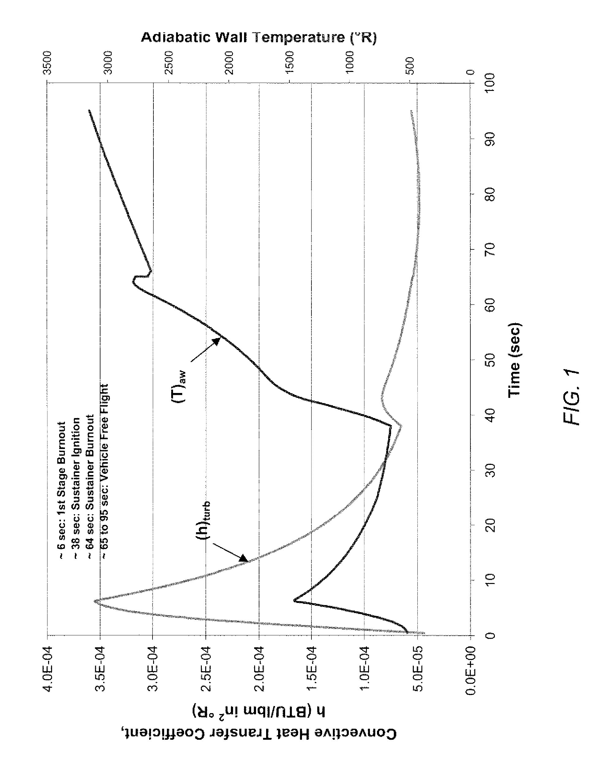
Such large variations in thermal loads impose tremendous demands on a vehicle thermal management system, typically requiring the cooling system to be designed for a fixed worst-case trajectory point.
Though this design approach may provide adequate cooling at the highest thermal loads point, it comes at the expense of potentially over-cooling at other “off-design” points.
This approach is inefficient, requires an undesirably high volume of coolant and places stringent demands on the thermal management system for the entire mission.
Similar inefficiencies may result from the spatial distribution of thermal loads over the surface of the structure being cooled.
Uncertainty in predicting the temperature at any particular location within a given structure (e.g., the inlet, combustor, or nozzle walls of an engine) will lead to conservative coolant flow rates for the entire structure.
Numerous other structures likewise function more effectively if maintained within a desired temperature range (or within other specified parameter limits) but suffer from similar inefficiencies in maintaining the desired parameters.

Method used


Image

  • Adaptive structures, systems incorporating same and related methods
  • Adaptive structures, systems incorporating same and related methods
  • Adaptive structures, systems incorporating same and related methods

Examples


example

[0065] Considering a long slender beam as an actuation device in an adaptive structure, a long slender beam in compression will exhibit a lateral deflection as the loading approaches a critical value and the beam becomes unstable. A beam with a perfectly symmetric cross section will buckle in a discontinuous manner at the critical load. A perfectly symmetric cross section, however, is a theoretical approximation. In reality, a compressive member will have some imperfection or asymmetry that leads to a continuous nonlinear deflection. Accordingly, the buckling of compressed beams with a designed eccentricity has been investigated, focusing on the regime of small eccentricity ratios, e / h→0 (e being the eccentricity or offset and h being the thickness of the beam), for the specific geometry shown in FIGS. 3A and 3B.

The Elastic Curve and the Secant Formulation

[0066] An elastic analysis of clamped-clamped beams under thermal loading was carried out with the assumption of small curvatu...


PUM

PropertyMeasurementUnit
diameteraaaaaaaaaa
thicknessaaaaaaaaaa
thicknessaaaaaaaaaa

Abstract

Adaptive structures, systems incorporating such adaptive structures and related methods are disclosed. In one embodiment, an adaptive structure is provided which includes a first structure and at least one microstructure associated with the first structure. The at least one microstructure may include a microscale beam configured to be displaced relative to the first structure upon the adaptive structure being exposed to a specified temperature. The beam may be formed for example, of a metallic material, of multiple different metallic materials, or of a shape memory alloy. In one embodiment, a plurality of the adaptive structures may be associated with micropores of a skin panel. The adaptive structures may be utilized to control the flow rate of a coolant or other fluid through the micropores responsive to a sensed environmental parameter such as, for example, temperature.

Description

CROSS-REFERENCE TO RELATED APPLICATION [0001] This application claims the priority filing date of U.S. Provisional Patent Application Ser. No. 60 / 733,980 filed Nov. 4, 2005, the disclosure of which is incorporated by reference herein in its entirety.FIELD OF THE INVENTION [0002] The present invention is related generally to adaptive structures, systems incorporating such adaptive structures and related methods. More particularly, the present invention is related to mechanisms and structures constructed and operative at the microscale that may be used individually or as part of a system for adapting and responding to environmental changes including time varying and location varying environmental parameters. BACKGROUND OF THE INVENTION [0003] There are numerous circumstances in which a structure experiences time varied and location varied state changes. Such state changes may be heavily influenced by the environment in which the structure is placed or is operating. For example, there ...

Claims


Application Information

Patent Timeline
Patent Type & Authority Applications(United States)
IPC IPC(8): C22F1/00
CPCB64C1/38B64C3/36B64C30/00B64G1/401B64G1/58Y10T137/1834Y10T137/1812
Inventor TILIAKOS, NICHOLASCASTROGIOVANNI, ANTHONY
Owner NORTHROP GRUMMAN SYST CORP
Why Eureka
Try Eureka