Gas Sensor Array with a Light Channel in the Form of a Conical Section Rotational Member

Inactive Publication Date: 2007-05-24
TYCO ELECTRONICS RAYCHEM GMBH
View PDF7 Cites 39 Cited by
  • Summary
  • Abstract
  • Description
  • Claims
  • Application Information

AI Technical Summary

Benefits of technology

[0006] It is therefore an object of the present invention to provide a gas sensor array of the type specified above, which h

Problems solved by technology

However, the array shown in this application has the disadvantage that the light efficiency is comparably

Method used


Image

  • Gas Sensor Array with a Light Channel in the Form of a Conical Section Rotational Member
  • Gas Sensor Array with a Light Channel in the Form of a Conical Section Rotational Member
  • Gas Sensor Array with a Light Channel in the Form of a Conical Section Rotational Member

Examples


Example

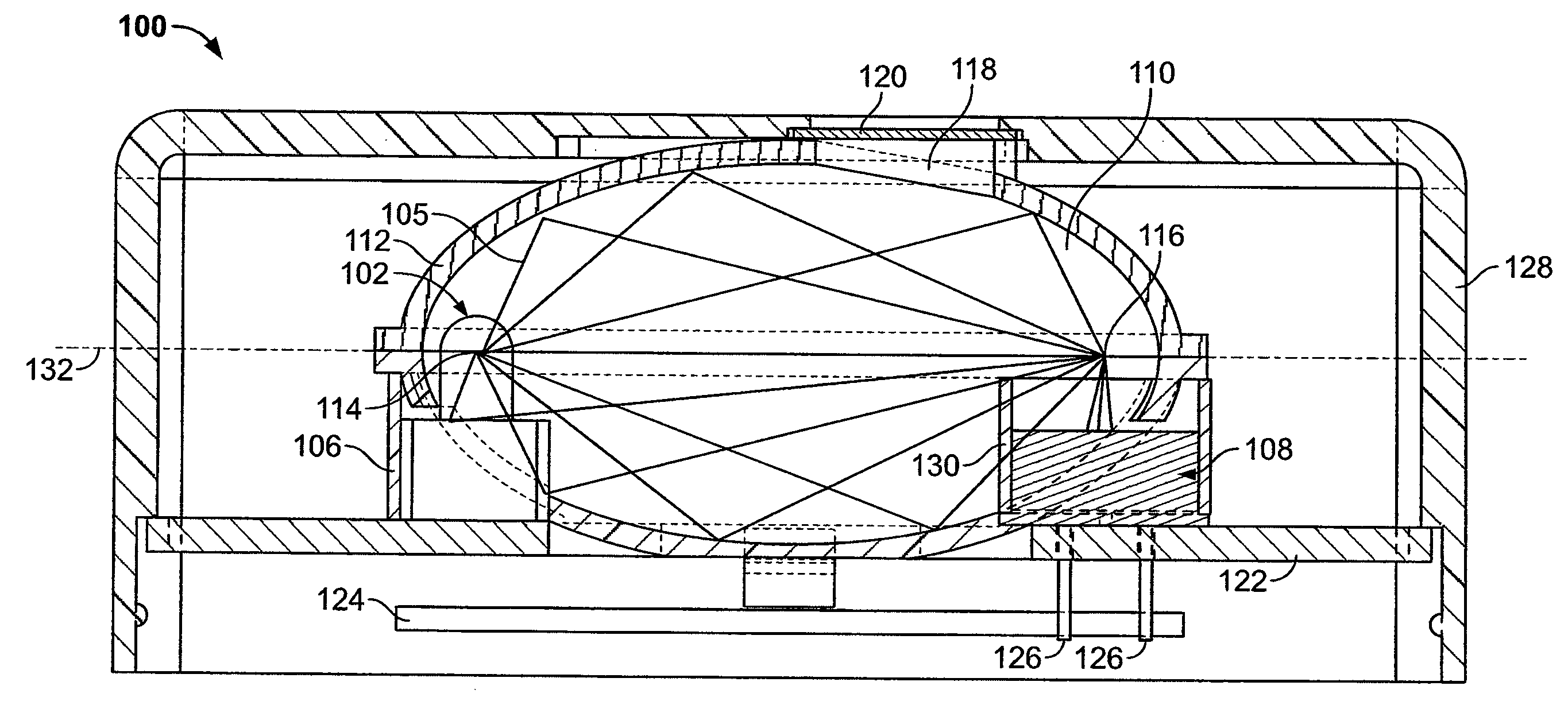
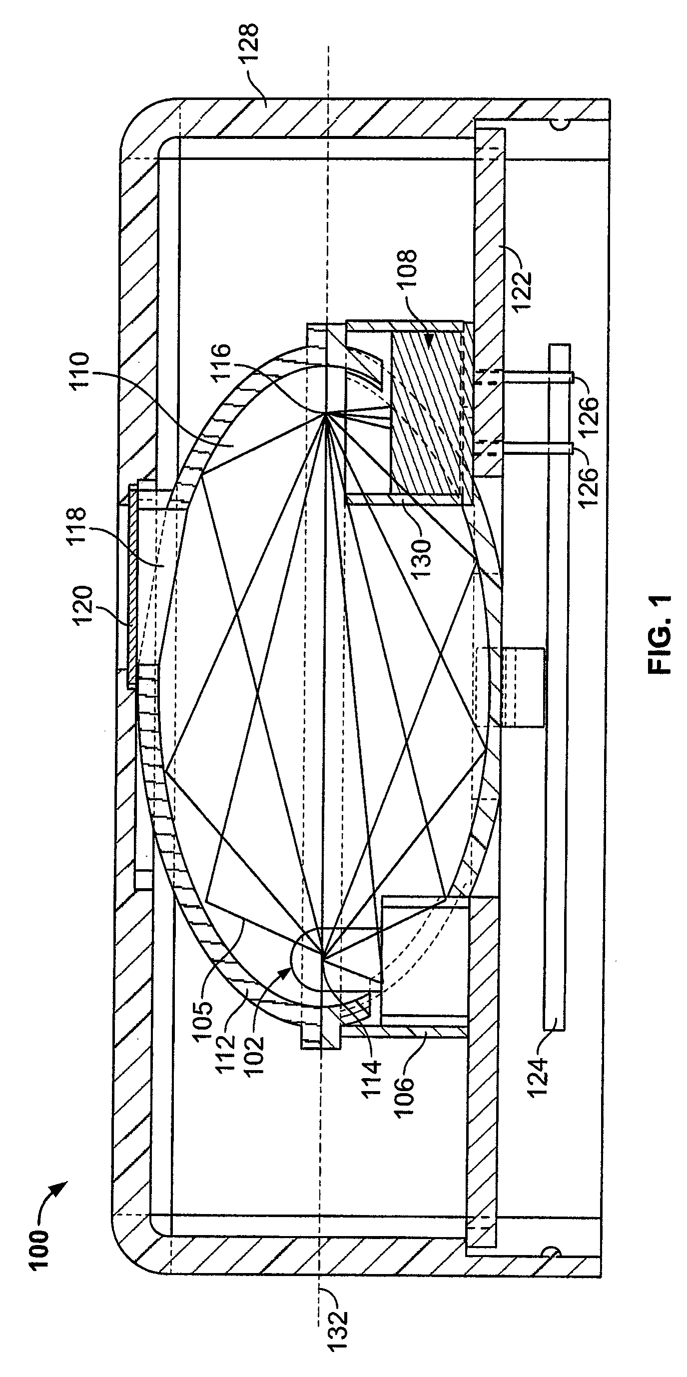
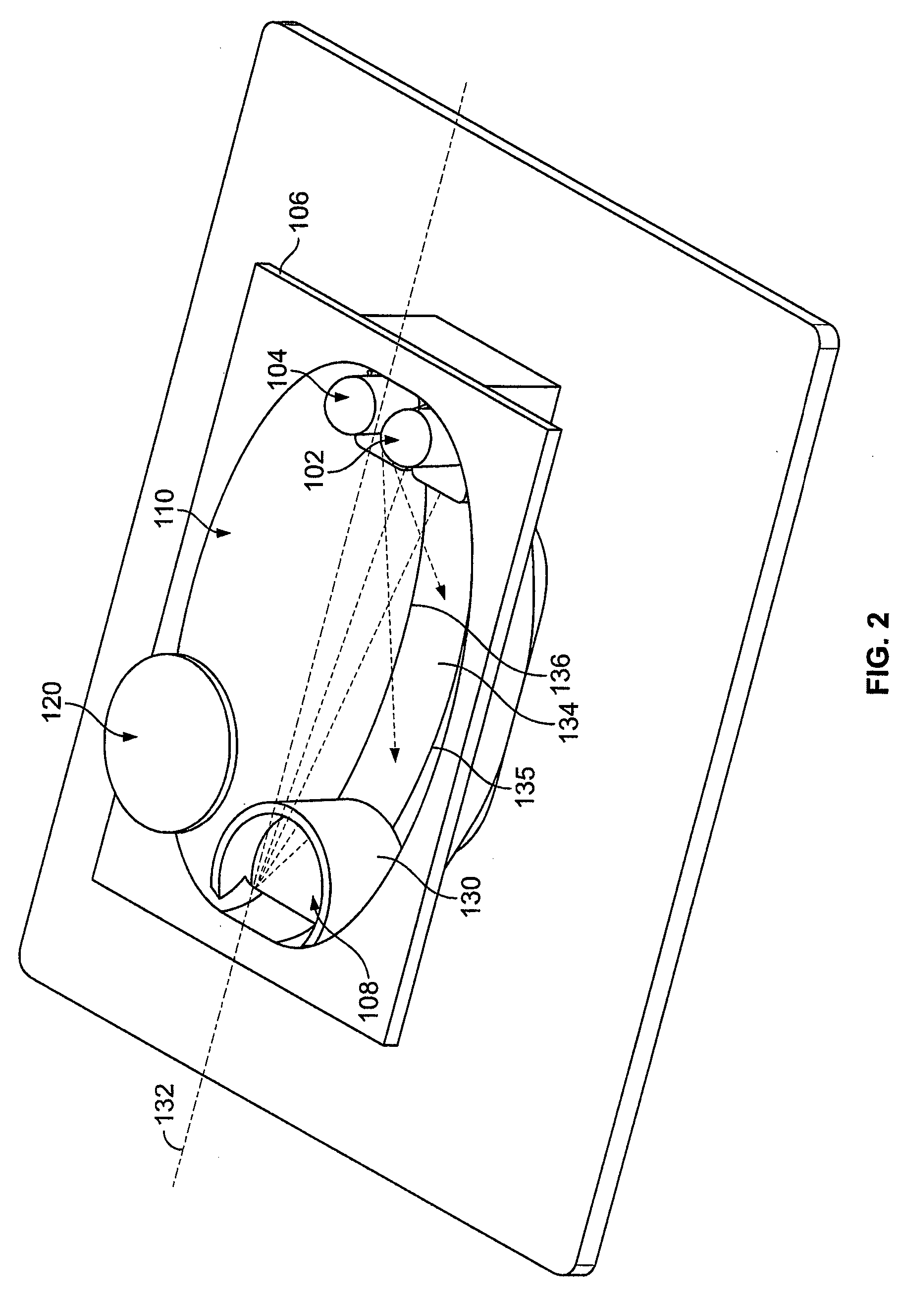
[0018]FIGS. 1-3 show a gas sensor array 100 according to a first embodiment of the invention. As shown in FIG. 1, the gas sensor array 100 comprises a housing consisting of a first half 106 joined with a second half 112. The housing may be formed, for example, from a plastic material using injection-molding. As shown in FIG. 2, infrared radiation sources 102, 104 are arranged in the first half 106 of the housing. The radiation sources 102, 104 may be, for example, lamps that emit broadband light spectrums or light-emitting diodes (LED), whereby the latter has the advantage that it is possible to dispense with filter arrays for wavelength selection. The radiation sources 102, 104 directs radiation or light rays 105 toward a detector 108 arranged in the first half 106 of the housing. The detector 108 may be, for example, a pyrodetector, which evaluates incoming radiation and supplies an electrical output signal as a function of the measured radiation. The detector 108 is provided with...

Example

[0026]FIGS. 4-7 show a second embodiment of a gas sensor array 100 according to the invention, which improves upon the gas sensor array 100 according to the first embodiment of the invention. As shown in FIG. 7, in the gas sensor array 100 according to the second embodiment, the connecting region 134 is formed so that the longitudinal limits 135, 136 of the connecting region 134 enclose an angle corresponding to an angle enclosed by center lines of the radiation sources 102, 104. In other words, the connecting region 134 has longitudinal limits 135, 136 corresponding to a center line extending between each of the radiation sources 102, 104 and the detector 108. This produces two rotationally elliptical regions of the gas measuring chamber 110, which have different first focal points 114, 115 but only one second focal point 116, which is located at the detector 108. A flat projection of the connecting region 134 has a substantially trapezoidal shape.

[0027] As shown in FIG. 4, the in...


PUM


Abstract

A gas sensor array includes a housing having a gas measuring chamber. A detector at least partially arranged in the gas measuring chamber measures radiation and generates an output signal as a function of the measured radiation. The detector is arranged on a main axis of the housing. Radiation sources are at least partially arranged in the gas measuring chamber and direct radiation toward the detector. The radiation sources are arranged symmetrically to the main axis at a first focal point and have the same effective radiation path length to the detector. The gas measuring chamber has at least one concave mirror formed by inner walls of the housing. The inner walls form a rotational member produced by a conical section and are configured to bundle the radiation emitted from the radiation source at a second focal point proximate the detector.

Description

FIELD OF THE INVENTION [0001] The present invention relates to a gas sensor array with at least one radiation source emitting radiation, a gas measuring chamber or light channel, which can be filled with a measuring gas that contains at least one analyte to be measured, and at least one radiation detector, which generates an output signal dependent on the presence and / or concentration of the analyte. In particular, the present invention relates to a miniaturized gas sensor array having the above-described elements that can be used, for example, in motor vehicles. BACKGROUND OF THE INVENTION [0002] Gas sensor arrays are known for the detection of a wide range of analytes, for example, methane or carbon dioxide, and are disclosed, for example, in European patent application EP 1 566 626 A1. These gas sensor arrays are based on the idea that many polyatomic gases absorb radiation, in particular in the infrared wavelength range. Such absorption occurs in a wavelength characteristic for ...

Claims


Application Information

Patent Timeline
IPC IPC(8): G01J5/02
CPCG01N21/0303G01N21/3504
Inventor MAEHLICH, REINHOLDMINUTH, RUDI
Owner TYCO ELECTRONICS RAYCHEM GMBH
Why Eureka
Try Eureka