Sterile de-molding apparatus and method

a technology of sterile de-molding and molds, applied in the field of sterile de-molding apparatus and methods, can solve the problems of more defectively filled containers than otherwise desired, time-consuming filling process, and high cost of processes and equipment, and achieve the effect of preventing contamination of molded parts

Inactive Publication Date: 2007-05-24
MEDINSTILL DEV
View PDF74 Cites 14 Cited by
  • Summary
  • Abstract
  • Description
  • Claims
  • Application Information

AI Technical Summary

Benefits of technology

[0027] Yet another advantage of the apparatus and method of the present invention is that the fluid disinfectant or sterilant sterilizes the surfaces of the mold that are not thermally sterilized by introduction of molten plastic into the mold, but that are located adjacent to the mold cavities to thereby prevent any germs or contaminants from collecting on such surfaces and, in turn, contaminating the molded sterile parts at the time of de-molding. A further advantage of the present invention is that the space between the mold portions is sterilized by the fluid disinfectant or sterilant, and when the mold portions are positioned in the fully-opened position for de-molding, the space between the mold portions is maintained aseptic or sterile by the substantially laminar flow of sterile gas through such space, thus enabling the assembly or other manipulation of the molded parts, such as containers and stoppers, in a sterile space, to thereby ensure the formation of sterile, sealed, empty container assemblies.
[0028] Yet another advantage of certain embodiments of the apparatus and method of the present invention is that the automated assembly device also is located within the aseptic or sterile space, and is maintained aseptic or sterile by the substantially laminar flow and / or overpressure of sterile gas through the space and over the assembly device to thereby maintain the assembly device aseptic or sterile and prevent contamination of the molded parts during assembly or other manipulation thereof
[0029] A still further advantage of a currently preferred embodiment of the present invention is that the sealed, empty, sterile container assemblies may be needle filled and laser resealed in line with the molding thereof to produce sterile, filled, sealed container and stopper assemblies.

Problems solved by technology

One of the drawbacks associated with such prior art container assemblies, and the processes and equipment for filling such container assemblies, is that the filling process is time consuming, and the processes and equipment are expensive.
Further, the relatively complex nature of the filling processes and equipment can lead to more defectively filled containers than otherwise desired.
In many cases, there are complex assembly machines for assembling the containers that are located within the aseptic area of the filling machine that must be maintained sterile.
This type of machinery can be a significant source of unwanted particles.
In closed barrier systems, convection flow is inevitable and thus laminar flow, or substantially laminar flow, cannot be achieved.
When operation of an isolator is stopped, a media fill test may have to be performed which can last for several, if not many days, and can lead to repeated interruptions and significant reductions in production output for the pharmaceutical, nutritional or other product manufacturer that is using the equipment.
In order to address such production issues, government-imposed regulations are becoming increasingly sophisticated and are further increasing the cost of already-expensive isolators and like filling equipment.
On the other hand, governmental price controls and marketplace competition for pharmaceuticals and vaccines, including, for example, preventative medicines, and other aseptically filled products, such as liquid nutrition products, discourage such major financial investments.
One of the drawbacks of gamma sterilization is that it can damage or otherwise negatively affect the parts to be sterilized, such as by discoloring parts formed of plastic and other gamma-sensitive materials.
In addition, if used to terminally sterilize filled containers, gamma radiation can damage the product stored within the container.
Accordingly, gamma sterilization has limited applicability, and further, is not always a desirable form of sterilization for many types of products with which it is used.
One of the drawbacks of such prior art filling machines and processes is that the fluid sterilant, such as vaporized hydrogen peroxide, necessarily must contact and sterilize the interior surfaces of the containers.
This, in turn, can lead to peroxidation or the formation of free radicals that can alter or otherwise degrade the product formulation during its shelf life, or that otherwise can degrade the taste or other qualities of the product in the container.

Method used


Image

  • Sterile de-molding apparatus and method
  • Sterile de-molding apparatus and method
  • Sterile de-molding apparatus and method

Examples


Embodiment Construction

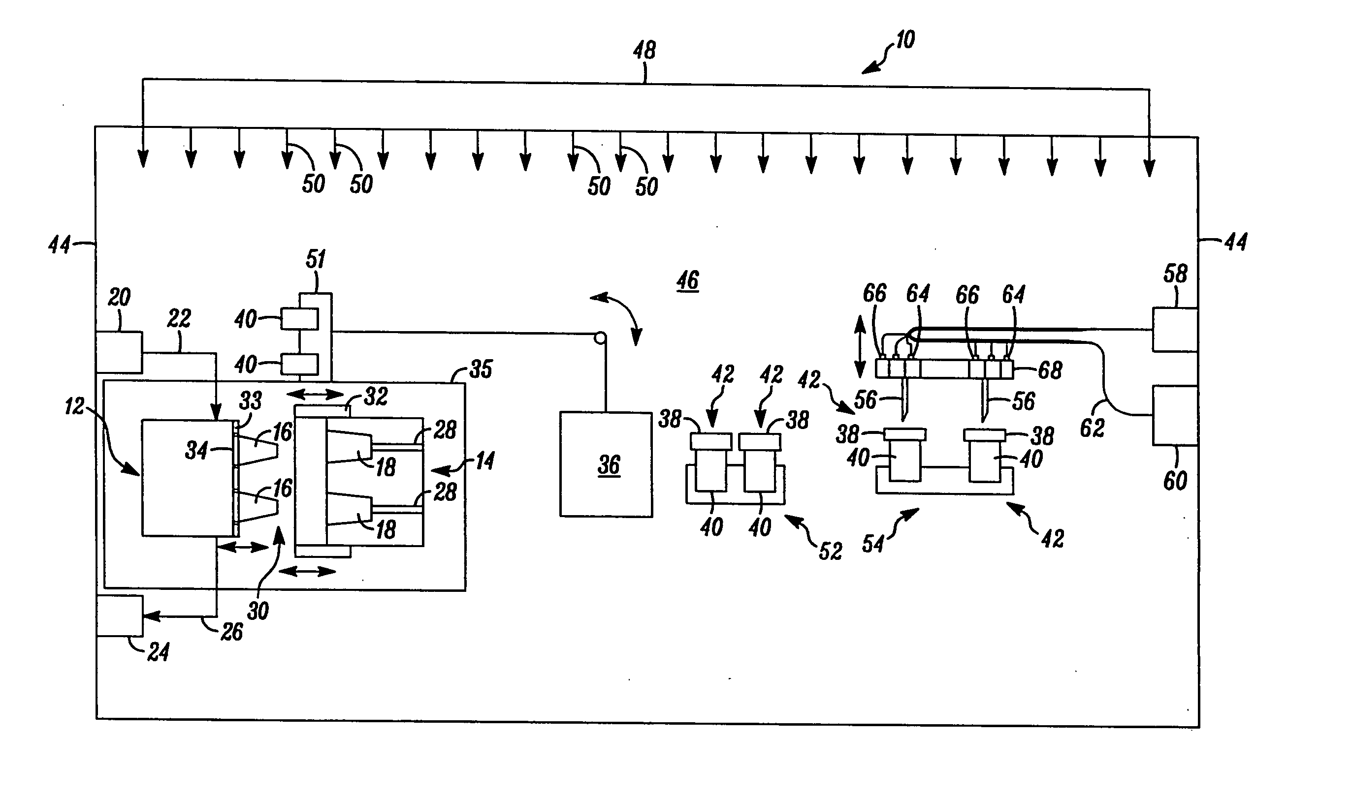
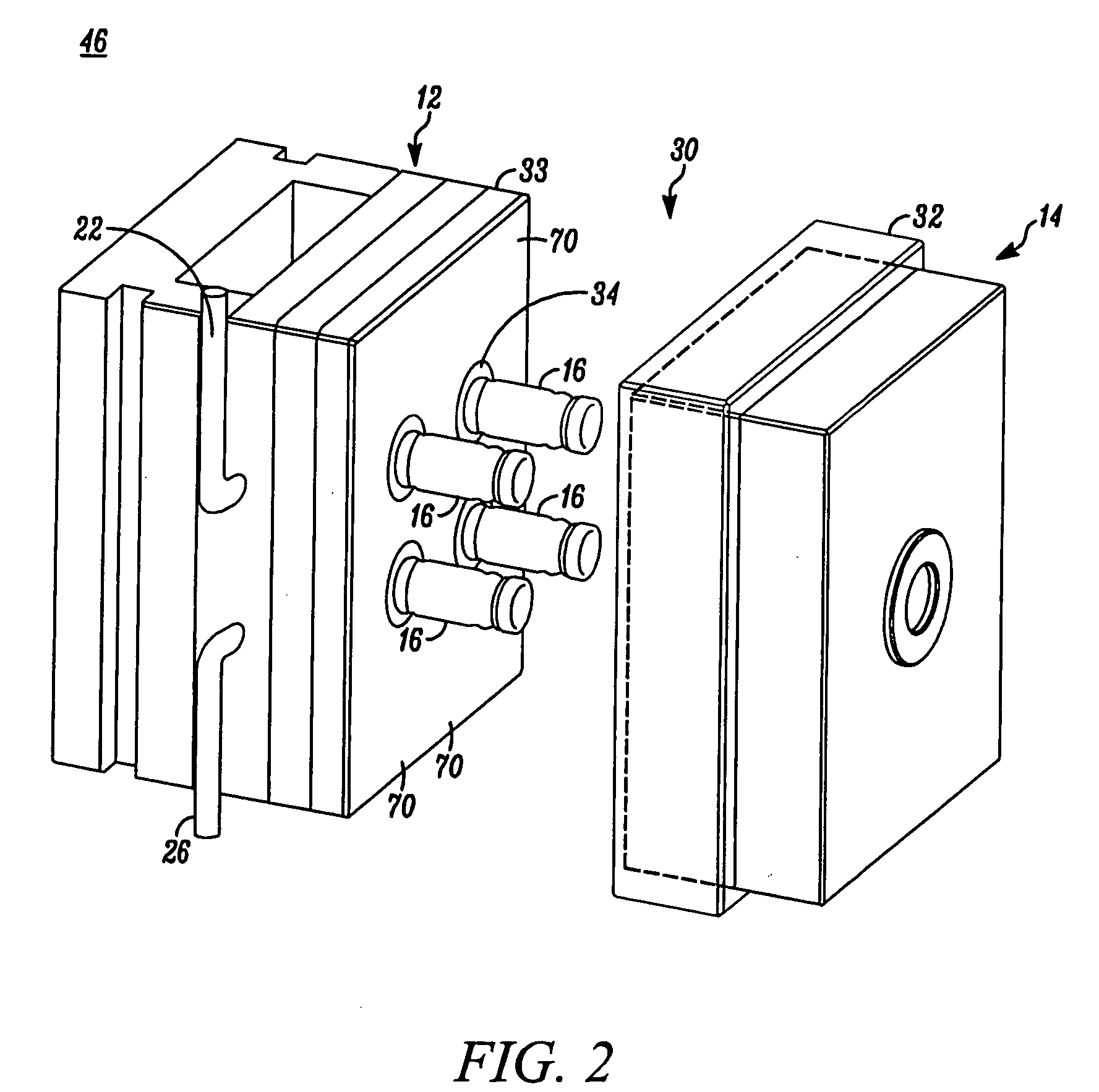
[0046] In FIG. 1, an apparatus embodying the present invention is indicated generally by the reference numeral 10. The apparatus 10 comprises a mold including a first mold half or portion 12, and a second mold half or portion 14. As indicated by the arrows in FIG. 1, at least one of the first and second mold portions 12 and 14 is movable relative to the other in a manner known to those of ordinary skill in the pertinent art between a closed position for molding the parts therein, and an open position for de-molding or releasing the molded parts therefrom. The first mold portion 12 defines a plurality of core pins 16 and the second mold portion 14 defines a plurality of corresponding cavities 18 for receiving therein the core pins 16. When the mold portions are located in the closed position, the core pins and mold cavities cooperate to define the mold cavity shapes for forming the parts therein, such as containers or stoppers. As may be recognized by those of ordinary skill in the p...


PUM

PropertyMeasurementUnit
vacuumaaaaaaaaaa
pressureaaaaaaaaaa
period of timeaaaaaaaaaa

Abstract

An apparatus and method are provided for molding sterile parts. The apparatus has a first mold portion and a second mold portion. At least one of the first and second mold portions defines a mold cavity configured to receive a molten plastic and form therefrom at least one molded part At least one of the first and second mold portions is movable relative to the other between (i) a closed position for sealing the mold cavity or cavities and molding at least one part therein, and (ii) an open position defining a fluid passageway between the first and second mold portions and permitting the passage of a fluid sterilant therein. A fluid source that contains or otherwise generates a fluid sterilant, such as vaporized hydrogen peroxide, is connectable in fluid communication with the fluid passageway for introducing the sterilant into the fluid passageway with at least one of the first and second mold portions in the open position, and in turn contacting with the sterilant the surfaces of the first and second mold portions forming the fluid passageway and located adjacent to the at least one mold cavity, but not contacting an interior surface of a molded part within the mold cavity, to sterilize the exposed mold surfaces and thereby prevent contamination of the molded part.

Description

CROSS-REFERENCE TO PRIORITY APPLICATION [0001] This patent application claims priority on U.S. provisional patent application Ser. No. 60 / 727,899, filed Oct. 17, 2005, entitled “Sterile De-Molding Apparatus And Method”, which is assigned to the Assignee of the present invention and is hereby incorporated by reference in its entirety as part of the present disclosure.FIELD OF THE INVENTION [0002] The present invention relates to apparatus and methods for molding aseptic or sterile parts, such as container assemblies having containers and stoppers for sealing openings in the containers, including polymeric stoppers that are needle penetrable for filling a closed container with a substance therethrough and that are laser resealable for laser resealing the needle penetrated region of the stopper, and more particularly, to apparatus and methods for molding, de-molding and assembling such parts under aseptic conditions. BACKGROUND OF THE INVENTION [0003] A typical aseptically filled conta...

Claims


Application Information

Patent Timeline
Patent Type & Authority Applications(United States)
IPC IPC(8): B29C45/00
CPCB29C37/0007B29C45/1701B29C45/1753B29C45/006B29C2045/1797B29C2791/005B29C45/42B29C45/40
Inventor PY, DANIELADAMO, BENOITGUTHY, JOHNHOULE, NATHANIELRODRIGUEZ, GIOVANNI
Owner MEDINSTILL DEV
Why Eureka
Try Eureka