Inductively-coupled RF power source

a power source and inductively coupled technology, applied in the direction of pulse automatic control, frequency to phase shift conversion, instruments, etc., can solve the problems of increasing the requirements of system functionality, increasing the requirements for increased device functionality and performance, and reducing the efficiency of analysis procedures, so as to achieve rapid changes in load impedance, effectively providing rf power, and tracking peak resonance conditions

Active Publication Date: 2007-05-24
THERMO ELECTRON MFG
View PDF7 Cites 82 Cited by
  • Summary
  • Abstract
  • Description
  • Claims
  • Application Information

AI Technical Summary

Benefits of technology

[0007] Therefore, if the impedance at the plasma coil changes as a result of a varying load from the test sample in the plasma torch, an error voltage is produced with a polarity that drives the operating frequency of the plasma coil in a direction towards resonance. The loop response of the phase-locked loop is only tens of cycles of the operating frequency. The R

Problems solved by technology

However, effectively performing analysis procedures with electronic devices may create substantial challenges for system designers.
For example, enhanced demands for increased device functionality and performance may require more system f

Method used


Image

  • Inductively-coupled RF power source
  • Inductively-coupled RF power source
  • Inductively-coupled RF power source

Examples


Embodiment Construction

[0019] The present invention relates to an improvement in analytical instrumentation techniques. The following description is presented to enable one of ordinary skill in the art to make and use the invention and is provided in the context of a patent application and its requirements. Various modifications to the disclosed embodiments will be readily apparent to those skilled in the art, and the generic principles herein may be applied to other embodiments. Thus, the present invention is not intended to be limited to the embodiments shown, but is to be accorded the widest scope consistent with the principles and features described herein.

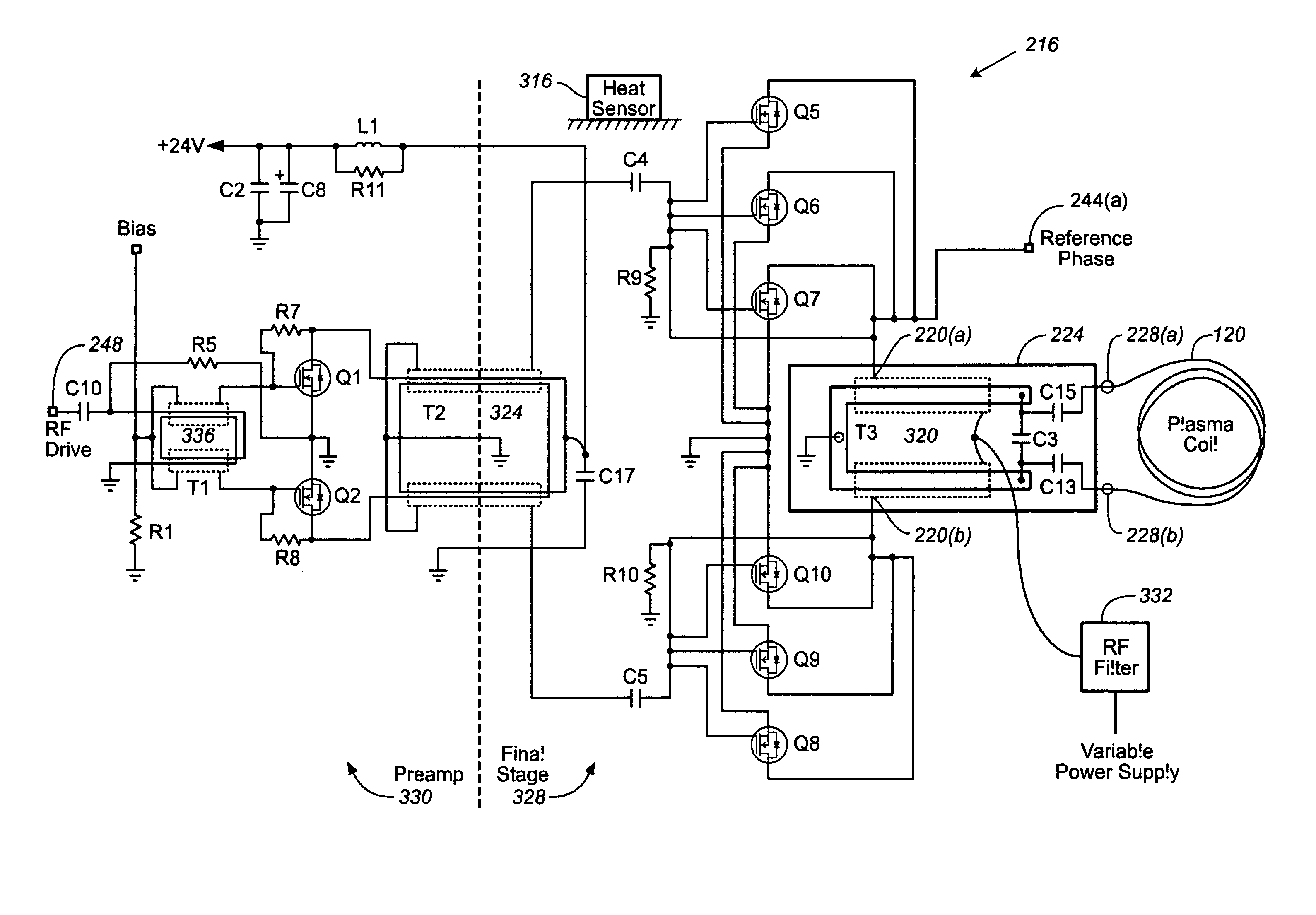
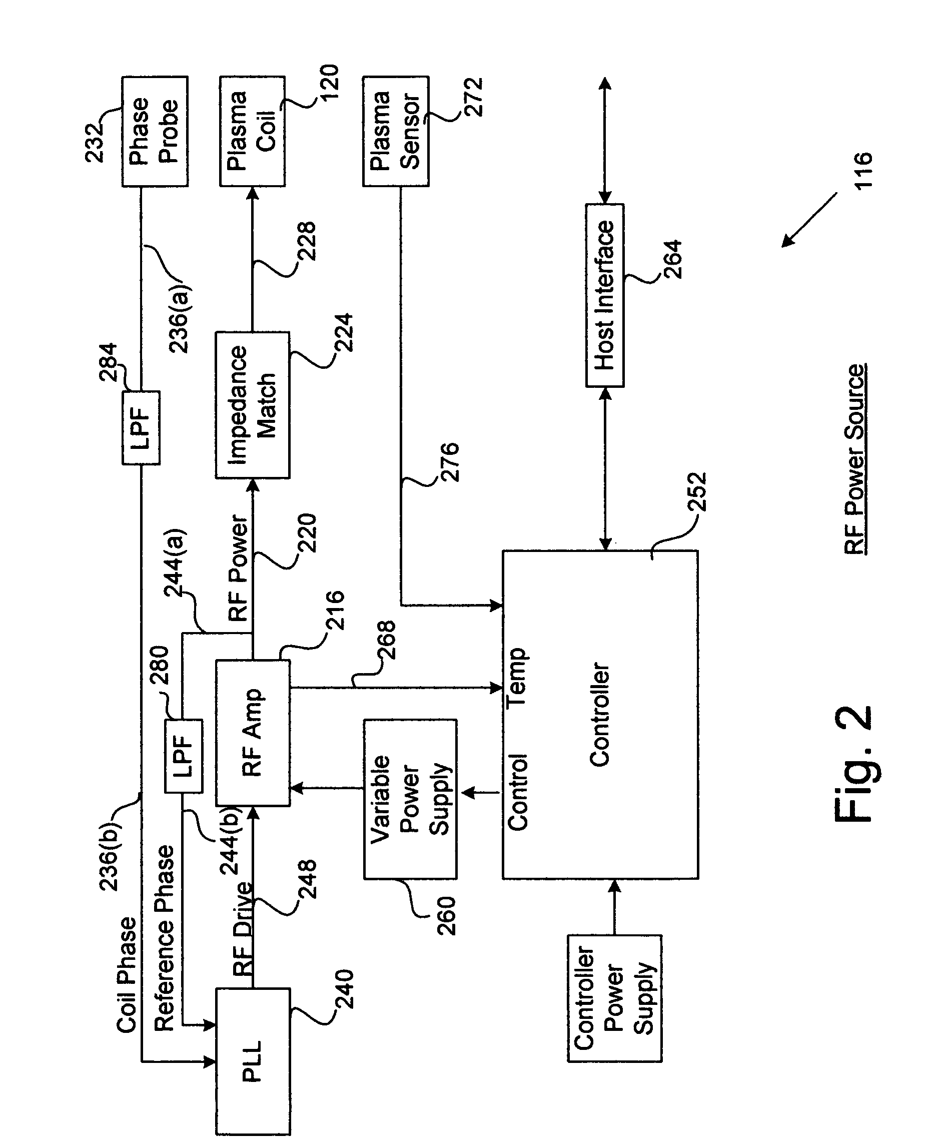
[0020] The present invention comprises a system and method for implementing a power source, and includes a power amplifier that generates a radio-frequency power signal with an adjustable operating frequency. The power amplifier also generates a reference phase signal that is derived from the radio-frequency power signal. An impedance match provide...


PUM


Abstract

A system and method are disclosed for implementing a power source including a power amplifier that generates a radio-frequency power signal with an adjustable operating frequency. The power amplifier also generates a reference phase signal that is derived from the radio-frequency power signal. An impedance match provides the radio-frequency power signal to a plasma coil that has a variable resonance condition. A phase probe is positioned adjacent to the plasma coil to generate a coil phase signal corresponding to the adjustable operating frequency. A phase-locked loop then generates an RF drive signal that is based upon a phase relationship between the reference phase signal and the coil phase signal. The phase-locked loop provides the RF drive signal to the power amplifier to control the adjustable operating frequency, so that the adjustable operating frequency then tracks the variable resonance condition.

Description

FIELD OF THE INVENTION [0001] The disclosed embodiments of the present invention relate generally to techniques for implementing a power source, and relate more particularly to a system and method for implementing an inductively-coupled plasma radio-frequency (RF) power source. BACKGROUND OF THE INVENTION [0002] Implementing effective methods for implementing analytical instrumentation is a significant consideration for designers and manufacturers of contemporary electronic analytical devices. However, effectively performing analysis procedures with electronic devices may create substantial challenges for system designers. For example, enhanced demands for increased device functionality and performance may require more system functionality and require additional hardware resources. An increase in functionality or hardware requirements may also result in a corresponding detrimental economic impact due to increased production costs and operational inefficiencies. [0003] Furthermore, e...

Claims


Application Information

Patent Timeline
IPC IPC(8): H01J7/24
CPCG01N21/73H01J37/321H01J37/32174H03L5/02H03L7/06H05H1/46
Inventor MATTABONI, PAUL J.MELLOR, ROBERTFLETCHER, ROGER
Owner THERMO ELECTRON MFG
Why Eureka
Try Eureka