Eureka AIR delivers breakthrough ideas for toughest innovation challenges, trusted by R&D personnel around the world.

Liquid crystal display

a liquid crystal display and liquid crystal technology, applied in non-linear optics, instruments, optics, etc., can solve the problems of reducing the effective area of the pixel, reducing contrast ratio or aperture ratio, and reducing aperture ratio, so as to suppress the reduction of the aperture ratio and high picture quality

Inactive Publication Date: 2007-05-24
PANASONIC LIQUID CRYSTAL DISPLAY CO LTD +1
View PDF7 Cites 18 Cited by
  • Summary
  • Abstract
  • Description
  • Claims
  • Application Information

AI Technical Summary

Benefits of technology

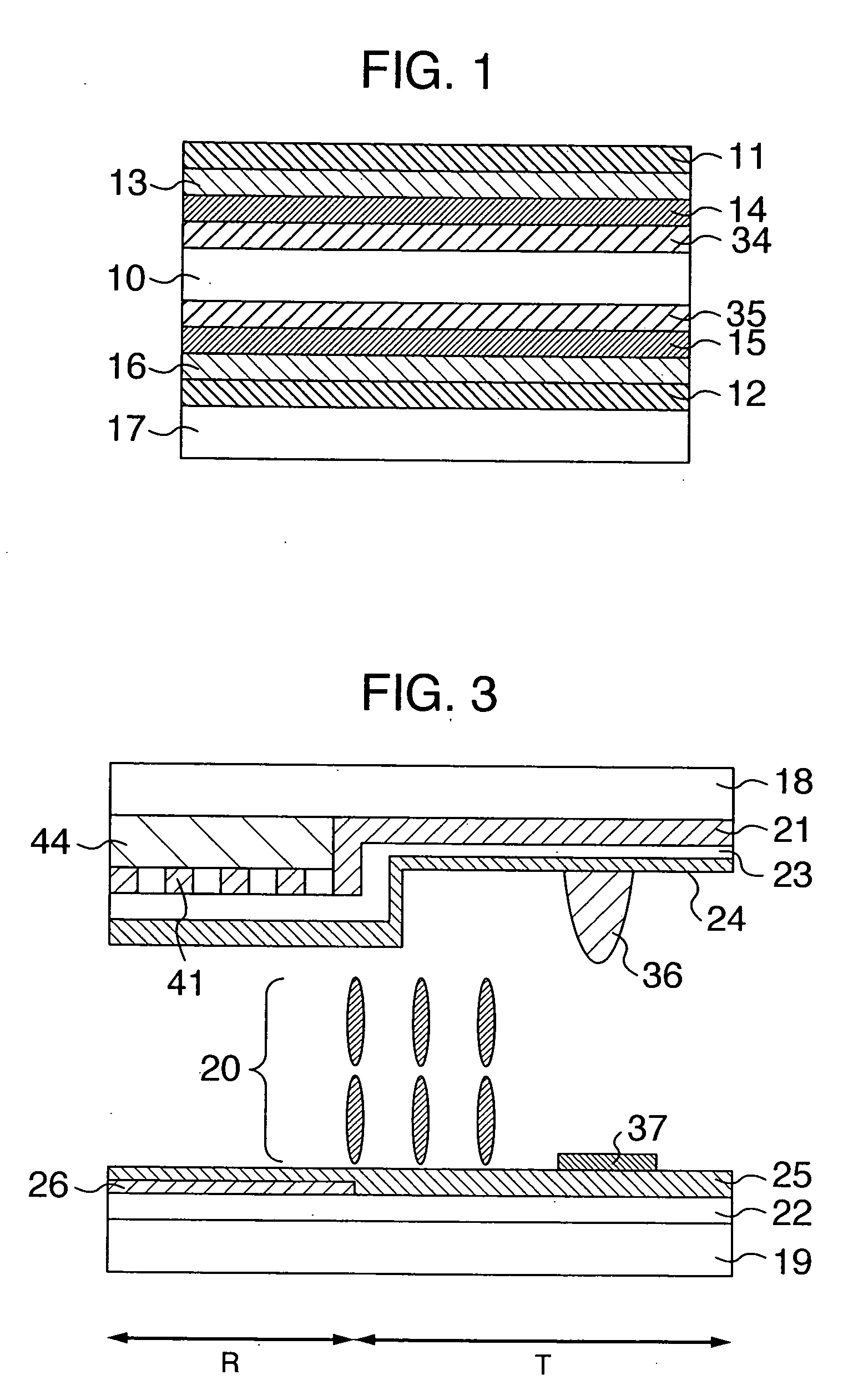
[0006] As described above, the transflective liquid crystal display can obtain satisfactory visibility in various surroundings of illumination. However, in order to optimize the retardations in the transmission area and the reflection area, it is necessary to provide the step structure in the reflection area. There arises a problem that the step structure reduces an effective area in the pixel and the contrast ratio or the aperture ratio is further reduced due to disturbance in alignment of the liquid crystal caused by the step structure.
[0007] Moreover, in the transmissive liquid crystal display of the VA system, since the pixel is divided into two parts or areas for the purpose of reduction in the γ-shift to make the two areas have different electro-optical characteristics, it is necessary to provide a new pixel capacity or new thin film transistor (TFT) and accordingly there is a problem that the aperture ratio is reduced and the cost is increased.
[0008] It is an object of the present invention to provide a liquid crystal display capable of displaying a picture with high picture quality without complicating pixel structure in one pixel while suppressing reduction in the aperture ratio.
[0015] There can be provided the liquid crystal display capable of displaying a picture with high picture quality without complicating the pixel structure in one pixel while suppressing reduction in the aperture ratio.

Problems solved by technology

There arises a problem that the step structure reduces an effective area in the pixel and the contrast ratio or the aperture ratio is further reduced due to disturbance in alignment of the liquid crystal caused by the step structure.
Moreover, in the transmissive liquid crystal display of the VA system, since the pixel is divided into two parts or areas for the purpose of reduction in the γ-shift to make the two areas have different electro-optical characteristics, it is necessary to provide a new pixel capacity or new thin film transistor (TFT) and accordingly there is a problem that the aperture ratio is reduced and the cost is increased.

Method used


Image

  • Liquid crystal display
  • Liquid crystal display
  • Liquid crystal display

Examples


embodiment 2

[0086] Another embodiment of a liquid crystal display according to the present invention is now described.

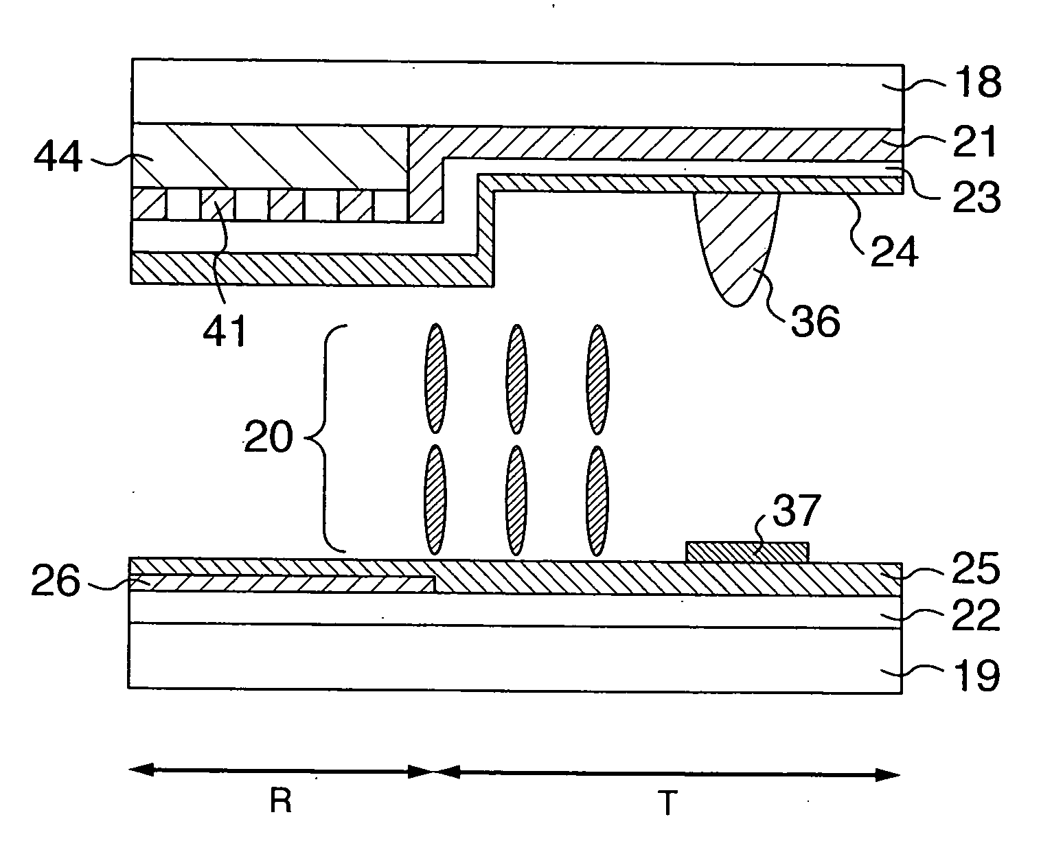
[0087] Description of the embodiment is directed to the transflective liquid crystal display of the electrically controlled birefringence (hereinafter abbreviated to ECB) system in which the liquid crystal molecules are aligned substantially horizontally to the substrate upon no application of voltage and aligned substantially vertically to the substrate upon application of voltage, wherein the ratio of common electrode 21 occupying the aperture in the transmission area is different from that in the reflection area and the ratio of the common electrode 21 occupying the aperture in the reflection area is equal to or larger than 0%-and smaller than 100%.

[0088] By using the liquid crystal display of the embodiment, the ratio dR / dT of the thickness dR of the reflection area and the thickness dT of the transmission area can be set to be equal to or larger than 0.5 and smaller than ...

embodiment 3

[0101] Another embodiment of a liquid crystal display according to the present invention is now described.

[0102] The liquid crystal display of the embodiment is directed to the transflective liquid crystal display of the VA system in which two-domain alignment is achieved to have high transmission factor. In the embodiment, the ratio of common electrode 21 occupying the aperture in the transmission area is different from that in the reflection area and the ratio of the common electrode 21 occupying the aperture in the reflection area is equal to or larger than 0% and smaller than 100% in the same manner as the embodiments 1 and 2. By using this liquid crystal display, the ratio dR / dT of the thickness dR of the reflection area and the thickness dT of the transmission area can be made equal to or larger than 0.5 and smaller than or equal to 1. Consequently, the aperture ratio can be improved and the cost can be reduced since the production process can be decreased.

[0103]FIG. 12 is a...

embodiment 4

[0108] Another embodiment of the second substrate of the liquid crystal display according to the present invention is now described.

[0109] In the transflective liquid crystal display of the embodiment, the ratio of the pixel electrode 22 occupying the aperture in the transmission area is different from that in the reflection area and the ratio of the pixel electrode 22 occupying the aperture in the reflection area is equal to or larger than 0% and smaller than 100%. By using this structure, the ratio dR / dT of the thickness dR of the reflection area and the thickness dT of the transmission area can be made equal to or larger than 0.5 and smaller than or equal to 1. Consequently, the aperture ratio can be improved and the cost can be reduced since the production process can be decreased.

[0110] The embodiment is different from the embodiment 2 in that the structure of the common electrode 21 and the pixel electrode 22 is changed and other fundamental structure is the same as that of ...


PUM


Abstract

A liquid crystal display having a plurality of pixels includes liquid crystal layer disposed between first and second substrates, first and second polarization plates disposed on the said opposite to the side where the liquid crystal layer is disposed with respect to the first and second substrates. The second substrate includes a pixel electrode on the side of the liquid crystal layer. Each of the plurality of pixels including a reflection area and a transmission area is different from a ratio of the common electrode occupying an aperture in the reflection area in a place of the pixel and the ratio of the common electrode occupying the aperture in the reflection area is equal to or larger than 0% and smaller than 100%.

Description

BACKGROUND OF THE INVENTION [0001] The present invention relates to a liquid crystal display and more particularly to a transflective liquid crystal display. [0002] A liquid crystal display is a non-light-emitting type display that displays a picture by adjusting an amount of transmitted light differently from a self-light-emitting type display represented by a cathode ray tube (CRT) and a plasma display panel (PDP). The liquid crystal display is characterized by thinness, light weight and low power consumption. [0003] As the liquid crystal display, there are a transmissive liquid crystal display that has a light source (hereinafter referred to as backlight) disposed at the back thereof and can adjust an amount of transmitted light from the light source to display a picture and a reflection liquid crystal display that utilizes external light such as indoor illumination and sunlight and makes the external light enter the display from the surface thereof so that an amount of reflected...

Claims


Application Information

Patent Timeline
IPC IPC(8): G02F1/1335
CPCG02F1/133371G02F1/133555G02F1/133707G02F1/134336G02F1/1393G02F2001/134318G02F2001/134345G02F2201/40G02F1/134318G02F1/134345
Inventor OKA, SHINICHIROADACHI, MASAYAKOMURA, SHINICHI
Owner PANASONIC LIQUID CRYSTAL DISPLAY CO LTD
Why Eureka
Eureka Blog
Learn More