Method and system for automatically determining regions in a scanned object

Active Publication Date: 2007-05-24
GENERAL ELECTRIC CO
View PDF22 Cites 21 Cited by
  • Summary
  • Abstract
  • Description
  • Claims
  • Application Information

AI Technical Summary

Problems solved by technology

Marking locations on the scout image can be a very time consuming and complex process that is dependent on the experience of the technologist.
This not only reduces scanning throughput, but can increase errors, for example, based on errors in the judgment of the technologist.
In addition, many potential dose management features are currently not practical or would be awkward and time consuming for the user because of the need to identify the required anatomic information.
For example, dose reduction for dose sensitive organs is currently not available on CT scanners.
Results can be adversely affected if portions of the neck or legs are included in the average, which can occur using known manual marking methods.
Different regions (such as the lungs) are manually identified on the graphic Rx display by a technologist and can result in including more anatom

Method used


Image

  • Method and system for automatically determining regions in a scanned object
  • Method and system for automatically determining regions in a scanned object
  • Method and system for automatically determining regions in a scanned object

Examples


Embodiment Construction

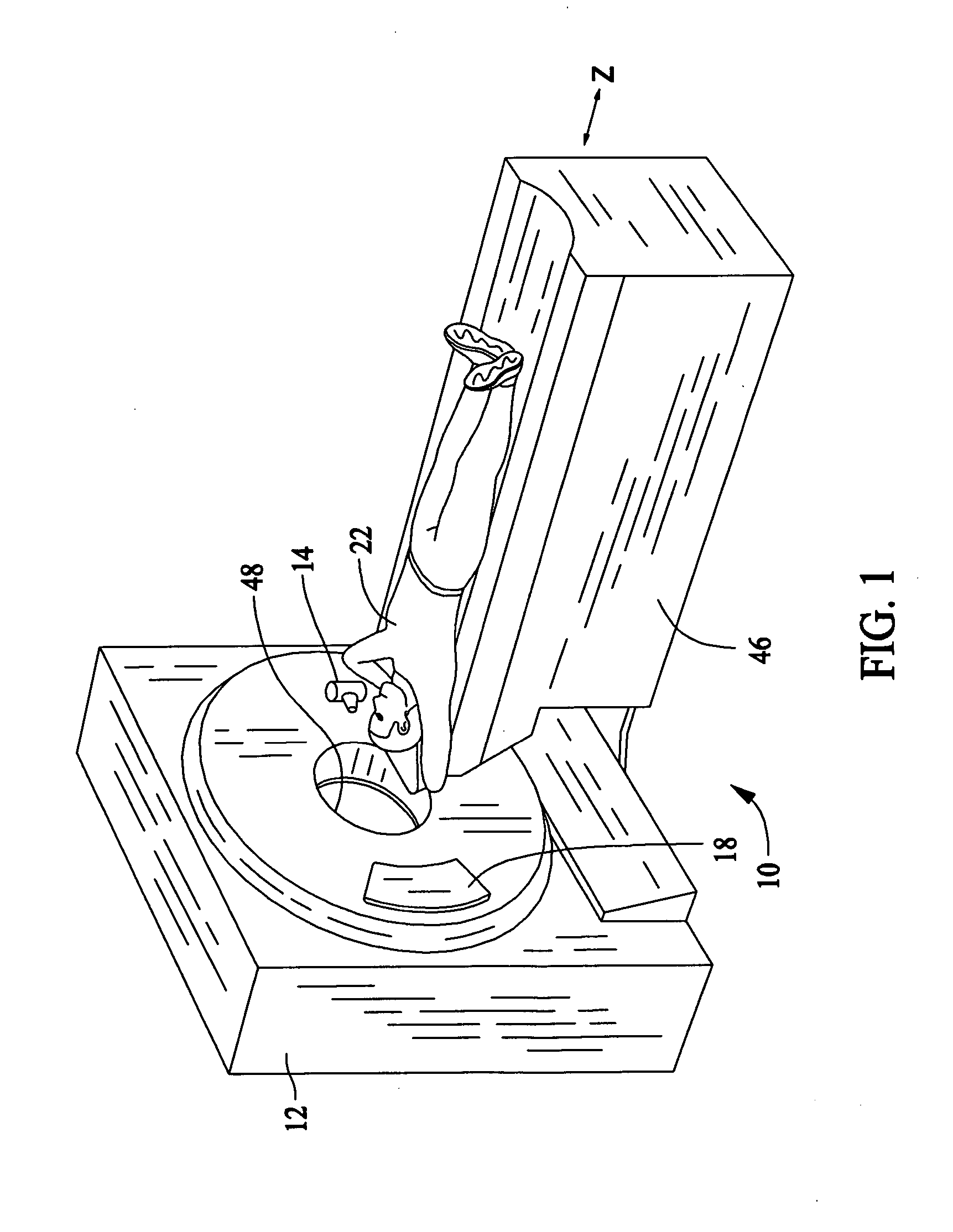
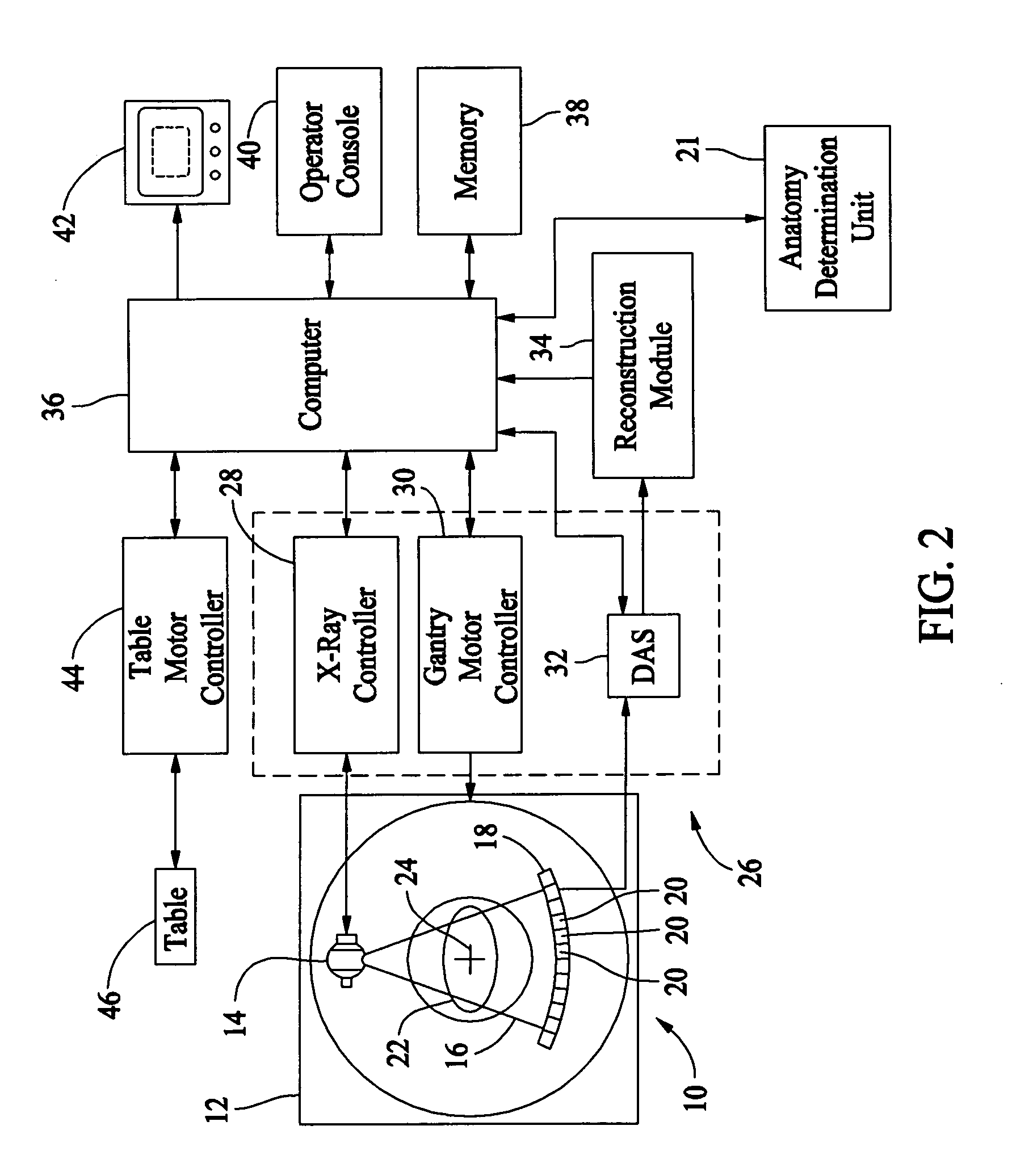
[0015]FIG. 1 is a perspective view of an exemplary imaging system 10. FIG. 2 is a schematic block diagram of the imaging system 10 (shown in FIG. 1). In an exemplary embodiment, the imaging system 10 is a single modality imaging system, for example, a computed tomography (CT) system. However, it should be understood that the various embodiments may be implemented in connection with imaging systems having more than one imaging modality (i.e., multi-modality imaging systems). Additionally, although the various embodiments may be described in connection with a particular imaging modality, for example, CT imaging, different imaging modalities both medical and non-medical may be used, for example, Positron Emission Tomography (PET), and in general any type of x-ray or nuclear imaging.

[0016] Referring now specifically to FIGS. 1 and 2, a computed tomography (CT) imaging system 10 is shown that includes a gantry 12 for a CT scanner. The gantry 12 includes an x-ray source 14 that projects ...


PUM


Abstract

A method and system for automatically determining regions in scanned object are provided. The method includes performing a scout scan of an object and automatically determining regions within the object based on attenuation information from the scout scan.

Description

BACKGROUND OF THE INVENTION [0001] This invention relates generally to methods and systems for imaging, and more particularly to methods and systems for automatically determining regions in a scanned object, particularly using medical imaging systems. [0002] Imaging systems are typically used to scan objects, and often are used to identify regions of interest within the objects. For example, in certain known computed tomography (CT) imaging systems, an x-ray source transmits x-ray beams through an object of interest. The x-ray beams pass through the object being imaged, such as a patient. The beams, after being attenuated by the object, impinge upon an array of radiation detectors. The intensity of the attenuated beam radiation received at the detector array is dependent upon the attenuation of the x-ray beam by the object. Each detector element of the array produces a separate electrical signal that is a measurement of the beam attenuation at the detector location. Attenuation meas...

Claims


Application Information

Patent Timeline
IPC IPC(8): G06K9/00
CPCA61B6/032A61B6/488G06T7/0081G06T11/005G06T2207/10081G06T2207/10116G06T2207/20012G06T2207/30004G06T7/11
Inventor TOTH, THOMAS LOUISDALY, MICHAEL PATRICK
Owner GENERAL ELECTRIC CO
Why Eureka
Try Eureka