

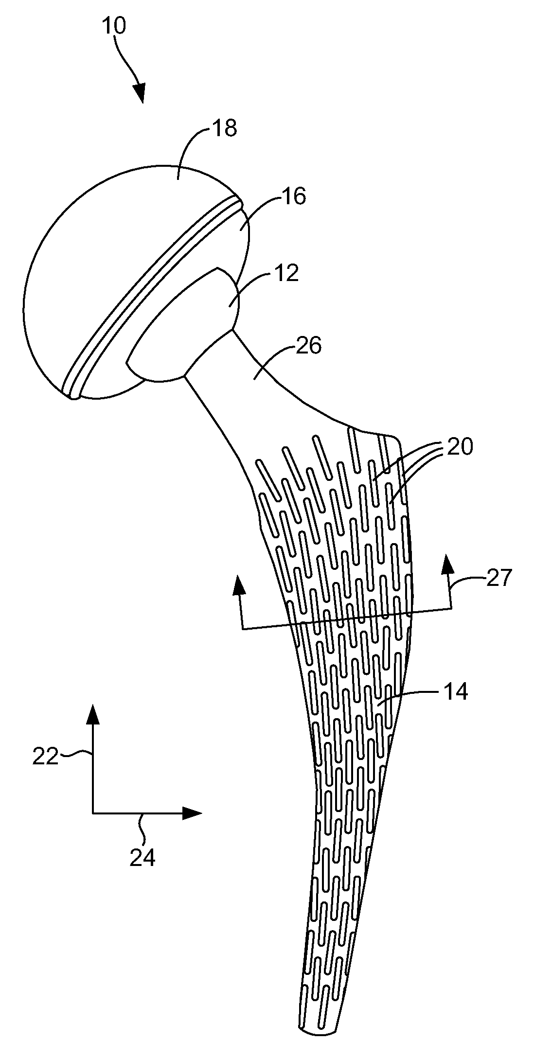
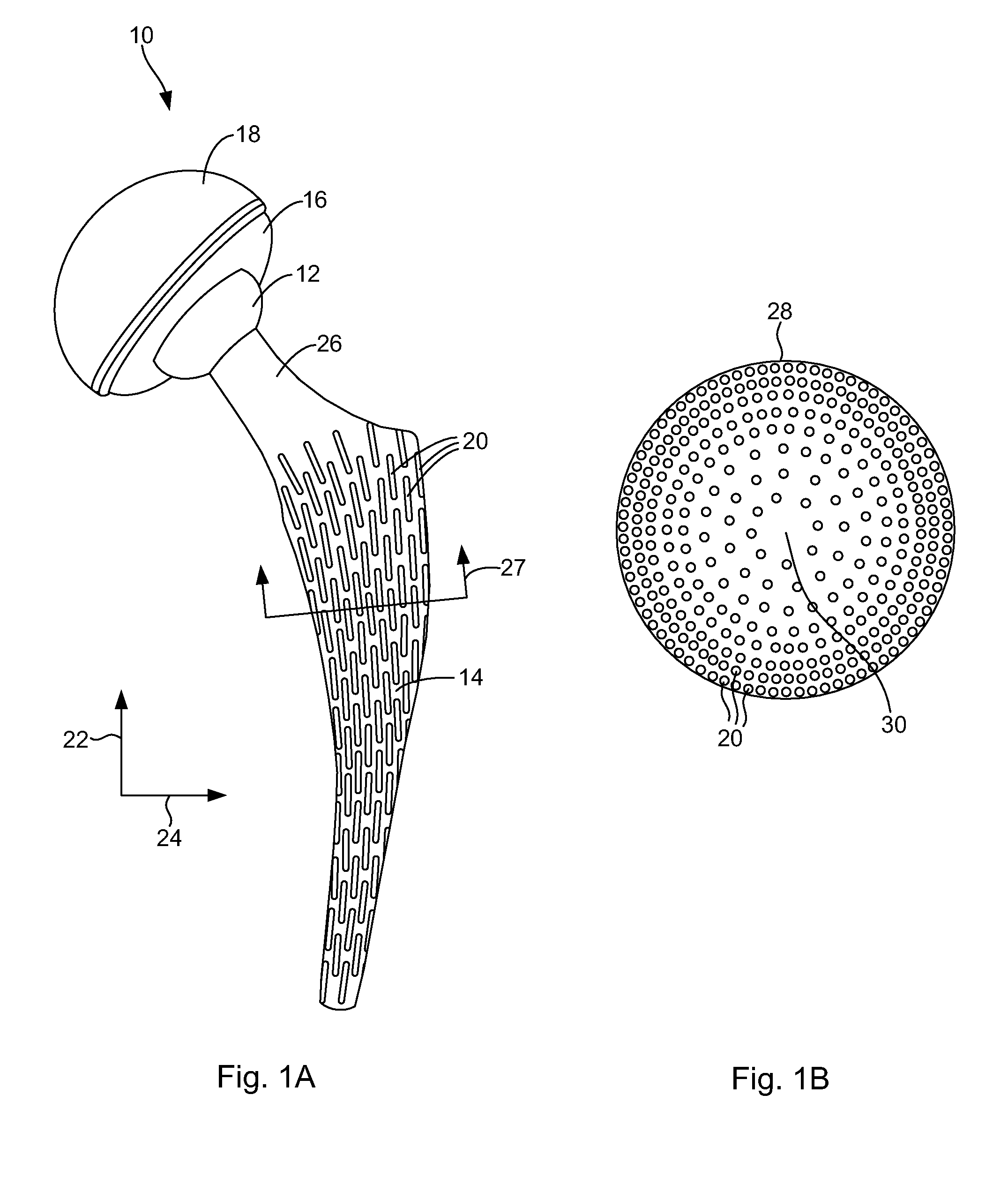
Porous, load-bearing, ceramic or metal implant
- Summary
- Abstract
- Description
- Claims
- Application Information
AI Technical Summary
Benefits of technology
Problems solved by technology
Method used
Image

Examples
example 1
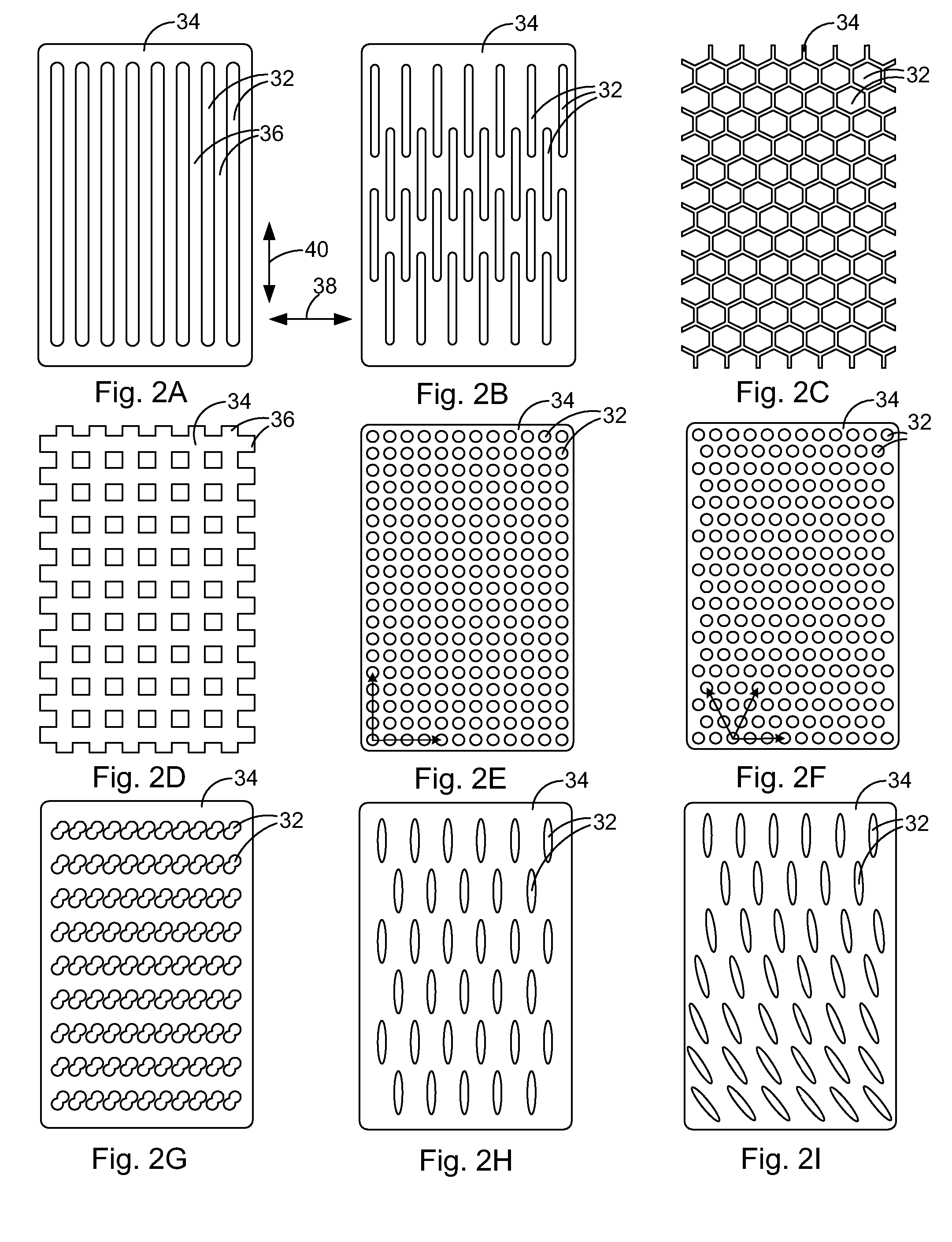
[0057] In a first example, ceramic alumina powder is mixed with water with the powder comprising about twenty to twenty-five percent of the total volume. A dispersant comprising less than one percent of the total weight is added to the mixture. PVA and glycerin are added to the mixture in a ratio of about 2:1 to obtain a final slip. This slip is then tape cast to a thickness of about 10 mils (0.01 inches) and dried to obtain a flexible tape. The tape is then laser cut to obtain channels like those illustrated in FIG. 2A.
example 2
[0058] In a second example, ceramic perovskite powder is mixed with toluene-ethanol mixtures with the ceramic powder comprising about forty to fifty percent of the total volume. A dispersant comprising less than one percent of the total weight is added to the mixture. PVB and Santicizer® 160 are added to the mixture in a ratio of about 2:1 to obtain a final slip. This slip is then tape cast to a thickness of about 10 mils (0.01 inches) and dried to obtain a flexible tape. The tape is then laser cut to obtain channels in the tape. The individual laser cut sheets are then stacked and laminated at a pressure of less than about 10,000 PSI at 60° C. The green laminated structure is then fired to between about 1200° C. to 1500° C. to obtain a fired component that has a tailored pore structure built into the device.
PUM
| Property | Measurement | Unit |
|---|---|---|
| Temperature | aaaaa | aaaaa |
| Temperature | aaaaa | aaaaa |
| Fraction | aaaaa | aaaaa |
Abstract
Description
Claims
Application Information