
Electrochemical low ESR capacitor with connector

a low-esr, capacitor technology, applied in the direction of connection contact member material, fixed capacitor details, coupling device connection, etc., can solve the problems of high esr (equivalent series resistance) and high capacitance loss of dlcs

Inactive Publication Date: 2007-05-24
AVX CORP
View PDF6 Cites 0 Cited by
  • Summary
  • Abstract
  • Description
  • Claims
  • Application Information

AI Technical Summary

Benefits of technology

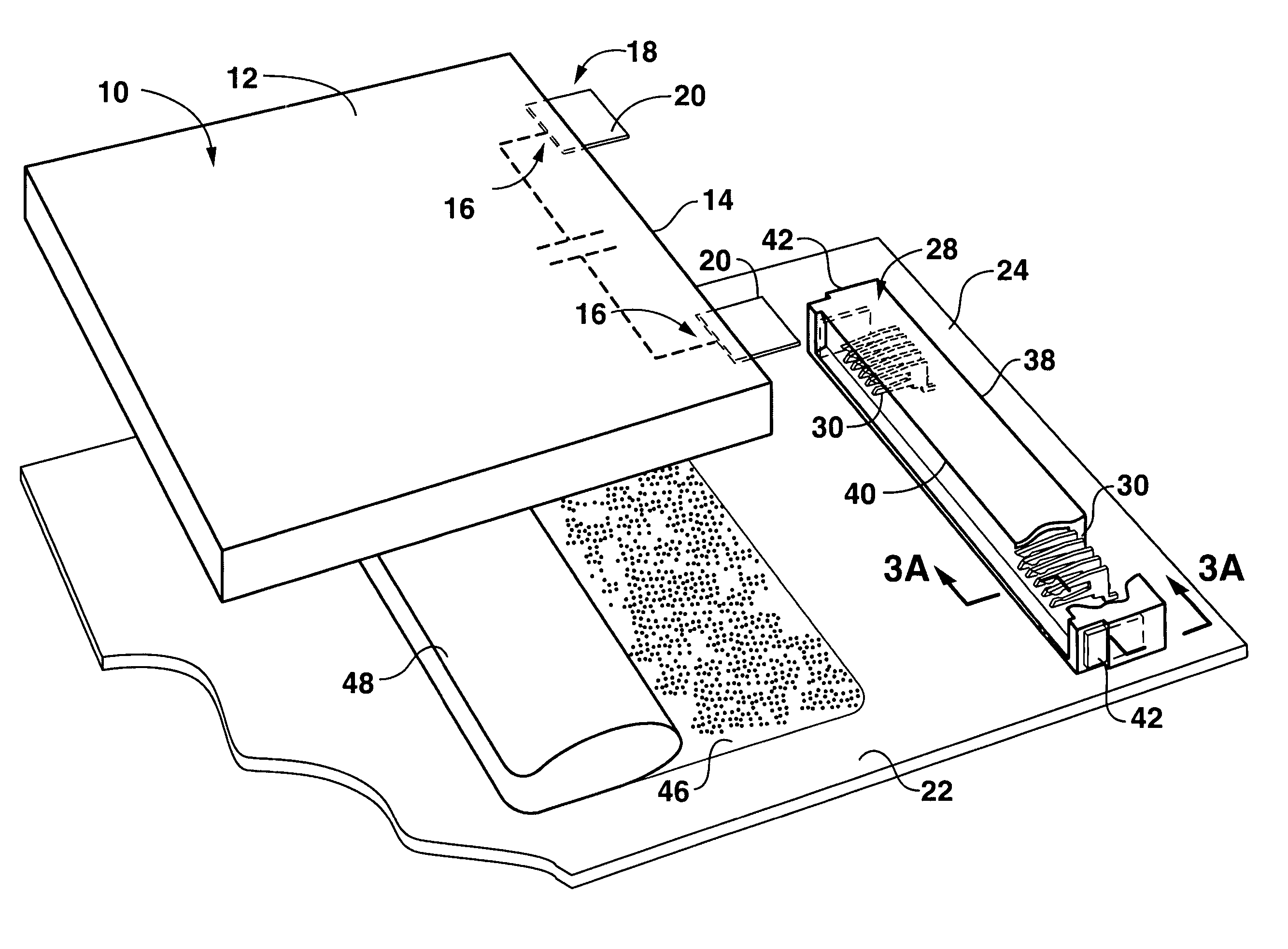
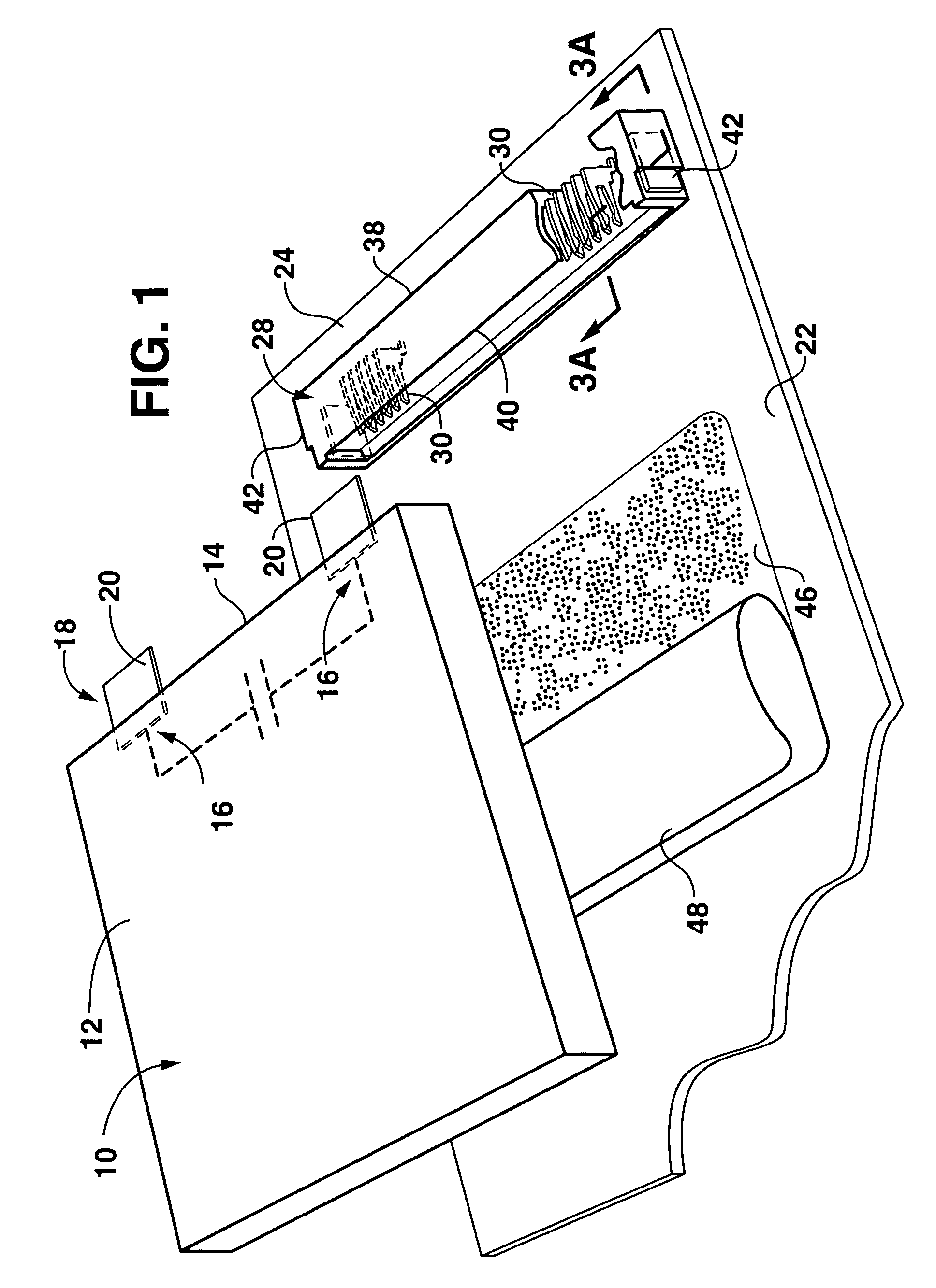
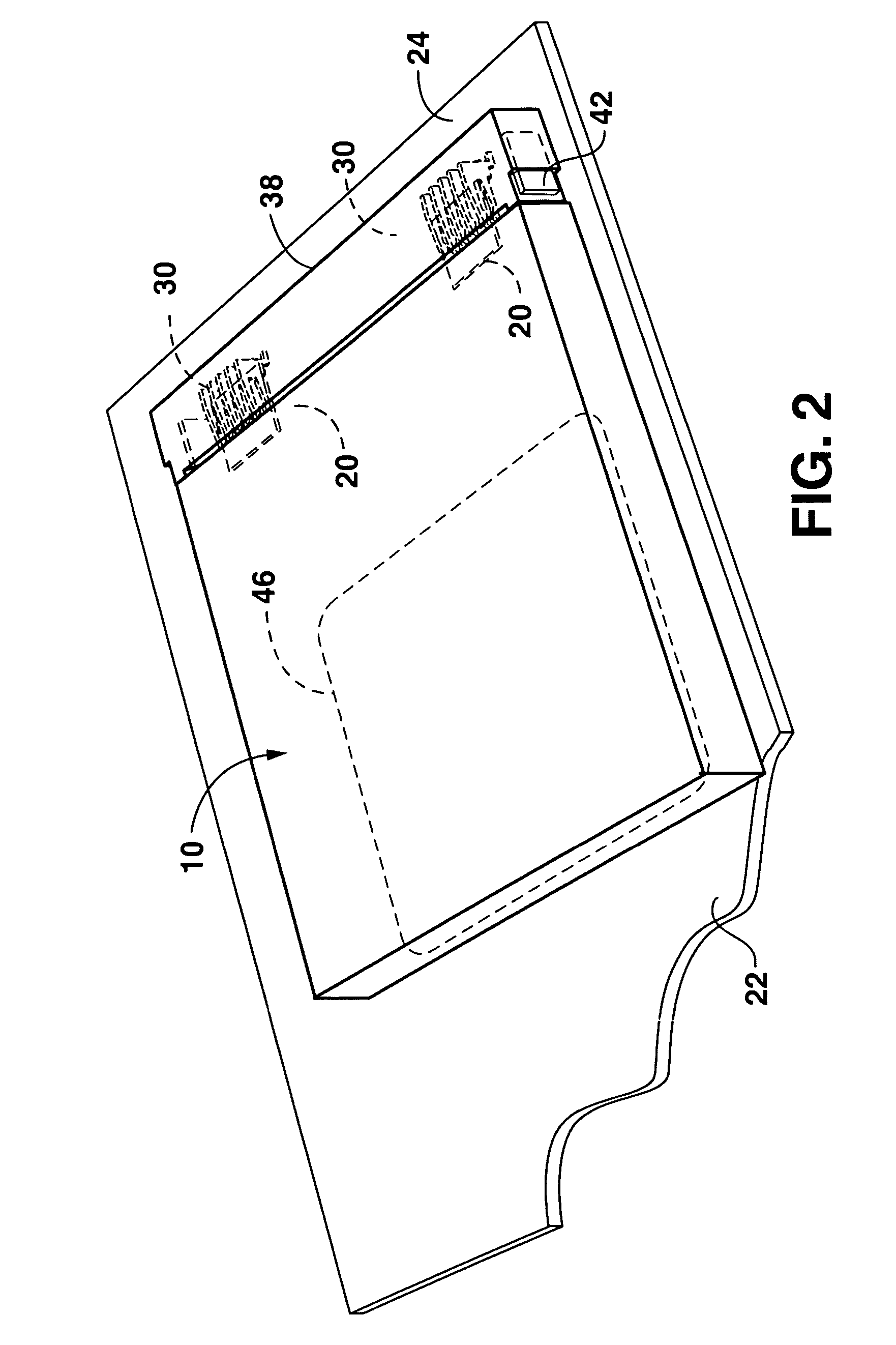
[0007] In accordance with aspects of the invention, a DLC capacitor is configured with a first connector component at its respective terminal leads. The first connector component mates with a corresponding second connector component mounted on a PCB using conventional techniques. This connector configuration allows the DLC to be easily pressed onto the PCB such that the first and second connector components mate. Hand or other soldering techniques are not needed to electrically mount the DLC onto the PCB, and the connector configuration does not add an appreciable increase in ESR.
[0014] It should be appreciated that any number of connector configurations are within the scope and spirit of the invention for mounting DLC capacitors to a PCB while satisfying the desired design criteria of minimizing ESR contribution at each DLC terminal.

Problems solved by technology

DLCs are generally subject to two limitations: high ESR (equivalent series resistance) and high capacitance loss when use to supply very short duration current pulses.
This combination produces a total voltage drop that may make the device unacceptable for certain applications.
This hand soldering step is an obvious detriment to efficient production of electronic components requiring a DLC.
Conventional connector arrangements that might be used to mount a DLC add an unacceptable contribution to ESR because of the lines and traces used for the socket / connector.

Method used


Image

  • Electrochemical low ESR capacitor with connector
  • Electrochemical low ESR capacitor with connector
  • Electrochemical low ESR capacitor with connector

Examples


Embodiment Construction

[0022] Reference now will be made in detail to various embodiments of the invention, one or more examples of which are set forth below. Each example is provided by way of explanation, not limitation of the invention. In fact, it will be apparent to those skilled in the art that various modifications and variations may be made in the present invention without departing from the scope or spirit of the invention. For instance, features illustrated or described as part of one embodiment, may be used on another embodiment to yield a still further embodiment. Thus, it is intended that the present invention cover such modifications and variations.

[0023] In accordance with aspects of the invention, a unique connector configuration is provided to mount a double layer electrochemical (DLC) capacitor to a printed circuit board (PCB). DLCs are known to those skilled in the art and a detailed explanation of these capacitors is not necessary for an understanding of the present invention. As ment...


PUM


Abstract

An electrochemical double layer capacitor (DLC) is configured for mounting on a PCB. A first connector component is configured at each individual terminal lead of the DLC capacitor. A second connector component is mounted on the PCB and includes a number of parallel connector elements at a footprint location for electrical mating contact with the DLC leads. The connector configuration produces a minimal increase in the ESR of the capacitor when mounted on the PCB.

Description

PRIORITY CLAIM [0001] The present application claims priority to Provisional Application Ser. No. 60 / 732,393, filed Nov. 1, 2005. BACKGROUND OF THE INVENTION [0002] Electrochemical or Double Layer Capacitors (DLC), also referred to as “Supercapacitors”, have gained wide acceptance in the art for providing a unique combination of characteristics, particularly high voltage, power, and capacitance densities. DLCs are an excellent compromise between dielectric capacitors, such as ceramic, tantalum, film, and batteries. DLCs are widely used in high power, pulse applications, such as in GSM, GPRS Edge, and PCS based systems, generally requiring several amps of current for a few milliseconds. DLCs are commonly used in combination with a battery to provide high momentary current requirements, with the battery providing the bulk total energy to the system and a trickle charge to the DLC when high current pulses are not required. [0003] DLCs are generally subject to two limitations: high ESR ...

Claims


Application Information

Patent Timeline
Patent Type & Authority Applications(United States)
IPC IPC(8): H05K1/00H01G2/02H01G4/228H01G11/00H01G11/74H01G11/78
CPCH01G2/06H05K3/301H05K3/305H05K2201/10015H05K2201/10325H05K2201/10462H05K2203/066Y02E60/13H01R12/716H05K3/32H05K2201/10189H05K2201/10962H01G11/82H01G9/155H05K1/181H05K3/325H01G11/74
Inventor SHINABERGER, LEESMITH, DEANANDERSON, TOMRAWAL, BHARAT
Owner AVX CORP
Learn More