
Laminated film

a technology of laminate film and film layer, applied in the field of laminate film, can solve the problems of plastic substrates posing a problem of causing misalignment and relatively low mechanical strength, and achieve the effects of excellent mechanical strength, low coefficient of thermal expansion, and excellent display quality

Inactive Publication Date: 2007-05-24
NITTO DENKO CORP
View PDF2 Cites 34 Cited by
  • Summary
  • Abstract
  • Description
  • Claims
  • Application Information

AI Technical Summary

Benefits of technology

[0015] As described above, a laminated film of the present invention is excellent in terms of mechanical strength and low coefficient of thermal expansion, as well as enabling an image display device to have excellent display quality.

Problems solved by technology

Whilst substrates of the above type are required to have a low coefficient of thermal expansion, plastic substrates may pose a problem of causing misalignment when forming, for example, electrodes or color filters, due to thermal shrinkage and expansion, since plastic has a higher coefficient of linear expansion than glass.
Although those of various active matrix driving types are recently used especially in the field of liquid crystal display devices thanks to the excellent display quality compared with passive matrix driving types, the above problem is more significant in the liquid crystal display devices of the active matrix driving types because they are required to have a lower coefficient of thermal expansion than the passive matrix driving types.
Another problem associated with plastic substrates is that the mechanical strength thereof is relatively low.

Method used


Image

  • Laminated film
  • Laminated film
  • Laminated film

Examples


example 1

[0106] An epoxy resin composition was prepared by stirring and mixing: as resin, 27 parts by weight (hereinafter referred only to parts) of 3,4-epoxycyclohexylmethyl-3,4-epoxycyclohexane carboxylate represented by the aforesaid formula (2) and 73 parts of a bisphenol A type epoxy resin (AER250, trade name (epoxy equivalent of 190); manufactured by Asahi Kasei Corporation) represented by the aforesaid formula (1); as a curing agent, 108 parts of methylhexahydrophthahc anhydride represented by the following formula (6); and as a curing accelerator, 3.75 parts of tetra-n-butylphosphonium o,o-diethylphosphorodithioate represented by the following formula (7).

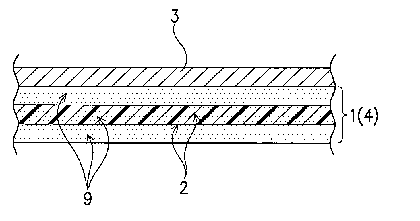
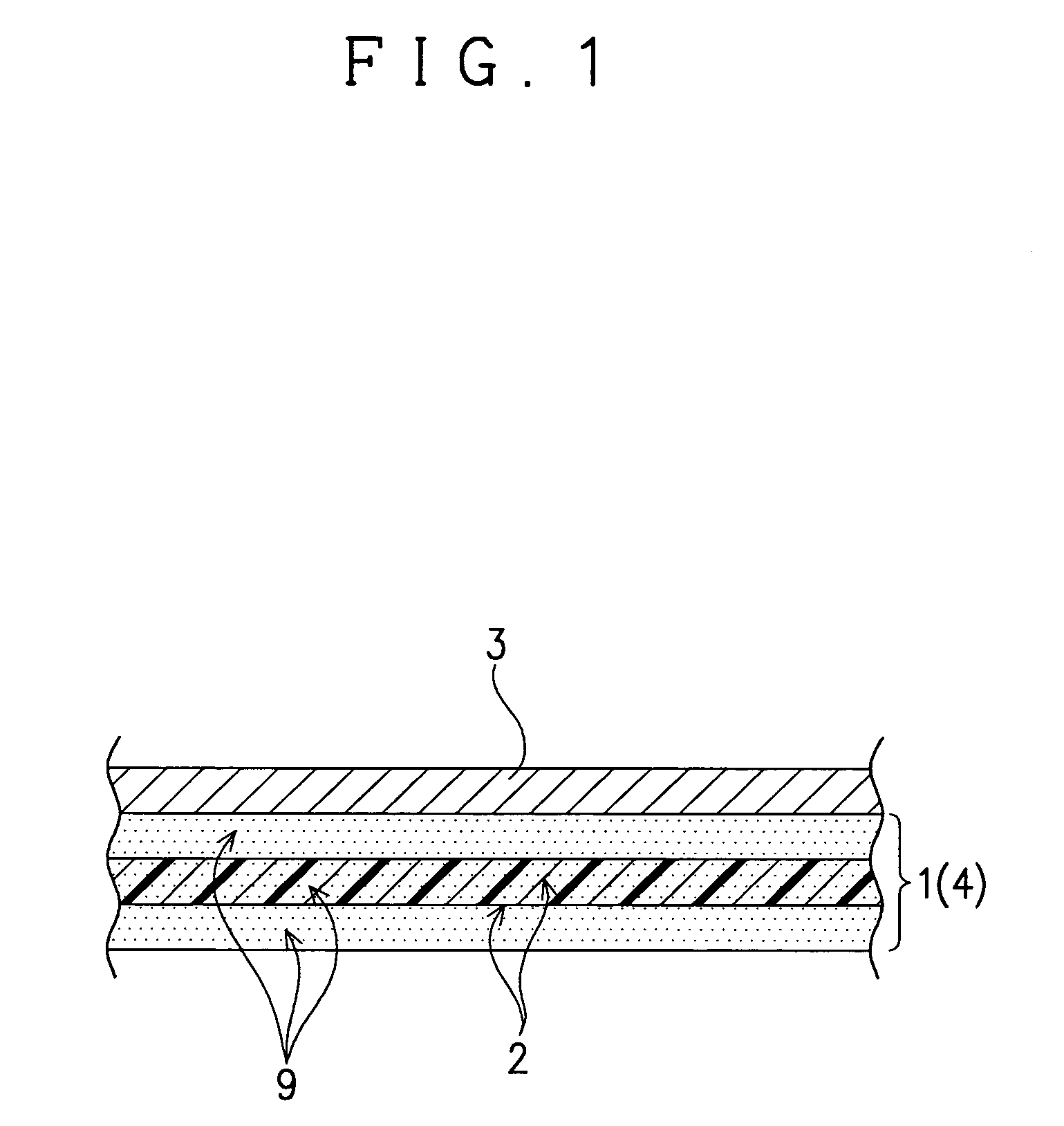
[0107] Then, the above epoxy resin composition was impregnated into glass cloth (“WLT116F”, trade name; manufactured by Nitto Boseki Co., Ltd.) using glass having a refractive index of 1.53, and left to stand for 10 minutes under a condition of a reduced pressure (200 Pa).

[0108] Then, a coating liquid, which was prepared by dissol...

example 2

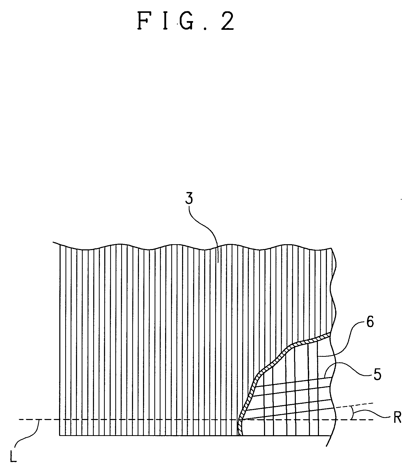
[0111] A laminated film of Example 2, which has weft yarn of glass cloth oriented at an angle of 3 degrees relative to an absorption axis of a polarizing plate, was obtained in the same manner as Example 1, except that the polarizing plate with a tackifier was cut into a rectangular shape to have an absorption axis oriented at an angle of 48 degrees relative to the long side.

example 3

[0112] A laminated film of Example 3, which has weft yarn of glass cloth oriented at an angle of 5 degrees relative to an absorption axis of a polarizing plate, was obtained in the same manner as Example 1, except that the polarizing plate with a tackifier was cut into a rectangular shape to have an absorption axis oriented at an angle of 50 degrees relative to the long side.


PUM

PropertyMeasurementUnit
softening pointaaaaaaaaaa
temperatureaaaaaaaaaa

Abstract

In the present invention, there is provided a laminated film that is excellent in terms of mechanical strength and low coefficient of thermal expansion. According to the present invention, there is provided a laminated film, which is characterized in that it comprises a resin sheet having a cured resin layer containing glass cloth and a polarizing plate laminated on the resin sheet, in which any one of weft yarn and warp yarn of the glass cloth is oriented at an angle of 5 degrees or less relative to an absorption axis of the polarizing plate.

Description

FIELD OF THE INVENTION [0001] The present invention relates to a laminated film used as a laminated body of a substrate and a polarizing plate, of a liquid crystal display device, an organic electroluminescence display device or the like. BACKGROUND OF THE INVENTION [0002] In the fields of image display devices, such as liquid crystal display devices and organic electroluminescence display devices, it is proposed to use plastic substrates in place of conventional glass substrates for progress in making displays lightweight, low-profile and high impact. [0003] Whilst substrates of the above type are required to have a low coefficient of thermal expansion, plastic substrates may pose a problem of causing misalignment when forming, for example, electrodes or color filters, due to thermal shrinkage and expansion, since plastic has a higher coefficient of linear expansion than glass. [0004] Although those of various active matrix driving types are recently used especially in the field of...

Claims


Application Information

Patent Timeline
Patent Type & Authority Applications(United States)
IPC IPC(8): B32B17/02B32B5/26B32B17/04B32B27/04G02B5/30G02F1/1333G02F1/1335H01L51/50H05B33/02
CPCB32B17/04B32B27/04B32B2307/42B32B2315/085B32B2457/20G02B5/3033G02F1/133305G02F1/133528G02F2001/133302G02F2202/023Y10T442/3065Y10T442/2992Y10T442/2926Y10T442/3707G02F1/133302G02B5/30B32B2307/7242B32B27/06B32B2305/72B32B2307/514B32B2260/021B32B2457/202B32B2457/206
Inventor SAKATA, YOSHIMASAAKADA, YUUZOUHARADA, TADAAKI
Owner NITTO DENKO CORP
Features
  • Generate Ideas
  • Intellectual Property
  • Life Sciences
  • Materials
  • Tech Scout
  • Unparalleled Data Quality
  • Higher Quality Content
  • 60% Fewer Hallucinations
Learn More