Transcutaneous power optimization circuit for a medical implant

a technology of optimizing circuit and cochlea, which is applied in the field of optimizing circuit in cochlear implant system, can solve the problems of short battery life, short battery life, and inability to satisfactorily assist patients with inner ear hearing impairment, and achieve the effect of increasing the life of external component batteries

Inactive Publication Date: 2007-05-24
COCHLEAR LIMITED
View PDF22 Cites 17 Cited by
  • Summary
  • Abstract
  • Description
  • Claims
  • Application Information

AI Technical Summary

Benefits of technology

[0012] A further objective is to provide a power control circuit for a cochlear implant which is constructed and arranged to automatically and dynamically regulate the inductive coupling with the internal component thereof to insure that power is not wasted, thereby increasing the life of the external component battery.

Problems solved by technology

Certain patients suffer from a hearing disability in the inner ear which cannot be satisfactorily assisted by normal hearing aids.
Because the internal component of the cochlear implant system is relatively small, it is not normally provided with its own permanent power supply.
Hence, there is an excess energy transfer across the link for patients with relatively smaller separation between the coils, or a low electrode-tissue interface impedance, resulting in a shorter battery life, than optimally desired.
Attempts have been made by others to resolve this problem but they have not been entirely satisfactory.
However, this approach is disadvantageous because it requires an RF transmitter having a variable programmable amplitude, and utilizes a fixed tuning of the transmit coil, therefore making no attempt to modulate the voltage on the tank capacitors to track the voltage required to maintain system compliance.
Obviously such a transmitter is expensive to make and more complex then a standard RF transmitter having a preset amplitude.
Moreover, sending information from the implantable section about the amplitude of the stimulation pulses after these pulses have already been applied is ineffective because, if one of these pulses is out of compliance, the external section can do nothing about it, except crank up the power to insure that future pulses are compliant.
However, merely cranking the power without any further intelligence wastes energy.

Method used


Image

  • Transcutaneous power optimization circuit for a medical implant
  • Transcutaneous power optimization circuit for a medical implant
  • Transcutaneous power optimization circuit for a medical implant

Examples


Embodiment Construction

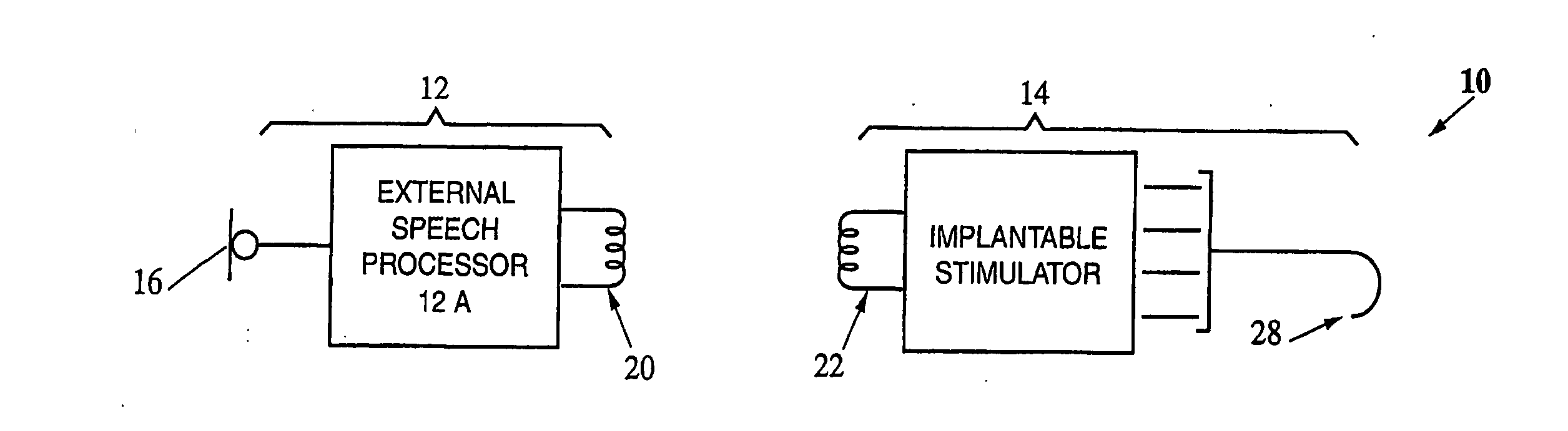
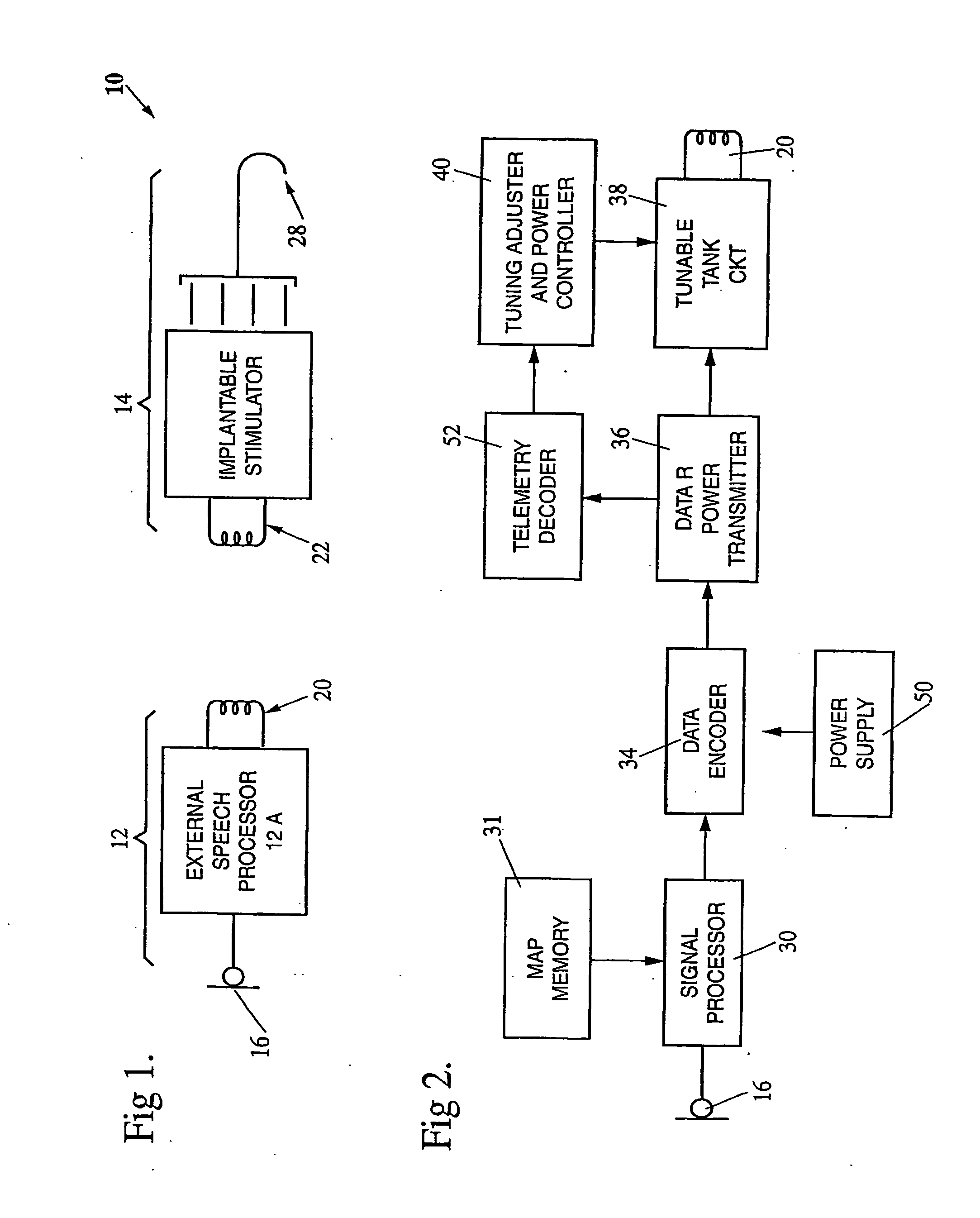
[0028] Referring first to FIG. 1, a cochlear implant system 10 constructed in accordance with this invention includes an external component 12 and an internal component 14. The external component includes a speech processor 12A and is associated with a microphone 16 for sensing ambient sounds and generating corresponding electrical signals. These signals are sent to the speech processor 12A which processes the signals and generates corresponding encoded signals. The encoded signals are provided to a transmitter (including a transmit coil 20) for transmission to the internal component 14.

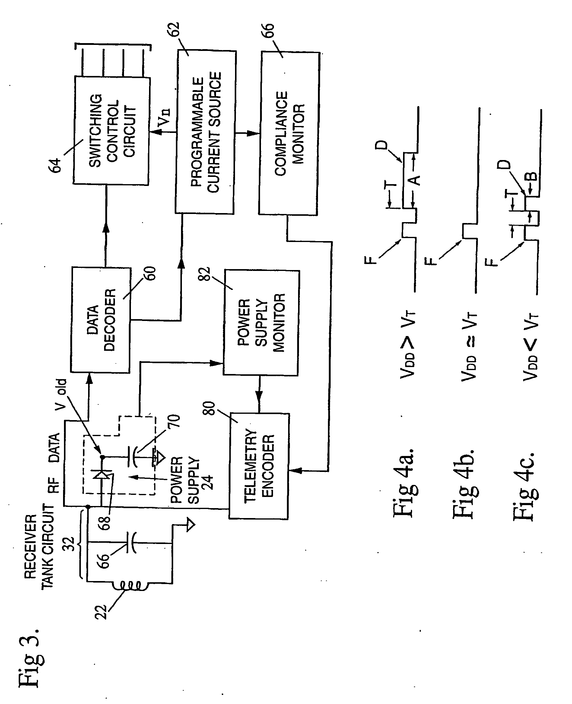
[0029] The internal component 14 (which may also be referred to as an implantable stimulator) receives the power and data via a receive coil 22. The RF power signal is stored by a power supply 24 (See FIG. 3) which provides power for the internal component 14. The data signals control the operation of the internal component 14 so as to generate the required stimulation pulses which are applied to th...


PUM


Abstract

In a cochlear implant system, the implantable stimulator includes a monitor which monitors parameters associated with the stimulation signals and / or the power stored in an energy storage element which stores energy transmitted from the processor. This parameter or parameters is / are analyzed and one or more feedback signals are generated and transmitted back to the processor. The processor uses the feedback signal to insure that power is transmitted to the stimulator optimally and that the stimulation signals are compliant.

Description

BACKGROUND OF THE INVENTION [0001] A. Field of Invention [0002] This invention pertains to an optimization circuit in a cochlear implant system and more particularly to a circuit which monitors one or more parameters within the implant such as the internal power supply level and the compliance of the stimulation signals applied by the implant. If an undesirable condition is indicated by these parameters, the circuit generates control signals to correct the condition by adjusting the coupling between the internal and external components of the system. [0003] B. Description of the Prior Art [0004] Certain patients suffer from a hearing disability in the inner ear which cannot be satisfactorily assisted by normal hearing aids. However, if the aural nerve is intact, the patient may have some aural functions restored with a cochlear implant system. A typical cochlear implant system presently available includes an external component or processor and an internal component often called the ...

Claims


Application Information

Patent Timeline
Patent Type & Authority Applications(United States)
IPC IPC(8): A61N1/00A61F11/00A61F2/18A61N1/18A61N1/372A61N1/378H04R25/00H04R25/04
CPCA61N1/37276A61N1/3787H04R25/606
Inventor SHAQUER, CEM M.
Owner COCHLEAR LIMITED
Why Eureka
Try Eureka