Implantable valve system

a valve system and implantable technology, applied in the field of implantable valve systems, can solve the problems of reducing the effective orifice area of the valve, irritating a large amount of the venous wall, causing trauma to the wall of the vein, etc., and achieving the effect of preventing back flow

Inactive Publication Date: 2007-05-24
BOSTON SCI SCIMED INC
View PDF47 Cites 80 Cited by
  • Summary
  • Abstract
  • Description
  • Claims
  • Application Information

AI Technical Summary

Benefits of technology

[0005] The valve element can have a curved surface, with the generally convex side of the valve element facing against the preferential direction of flow of fluid within the lumen in which the valve is placed. The opposite side of the valve element can consequently have a concave shape. A preferred embodiment of the valve element uses a frame to reinforce the element. The periphery is preferably soft, however, to prevent vessel wall damage. The valve element generally has a diameter in a range between 2 mm and 45 mm, and a thickness between 0.2 mm and 3.0 mm.
[0008] Alternately, the valve can have a base with a coinector to attach the valve to a lumen wall and a tubular wall connected to the base. The tubular wall has a proximal end with a proximal opening and a distal end with a distal opening. When implanted into a lumen, flow from the distal end to the proximal end forces the tubular wall into an open position thereby allowing flow through the tube while flow from the proximal end to the distal end forces the tubular wall into a closed position, thereby preventing flow in this direction. The valve can be shaped as a wedge shaped tube or as a curve shaped tube. The curve shaped tube can include a crease portion which allows the tube to collapse in the presence of back flow, thereby preventing back flow from entering the tube. The valve can be made from a silicone material.

Problems solved by technology

However, there remain many situations in which a valve is compromised to the extent that these options are not effective and valve replacement must be considered.
However, stents can reduce the effective orifice area of the valve which increases the transvalvular pressure gradient.
A further drawback to this valve is that a stent has fixed dimensions and remains in contact with the total circumference of the inner venous surface which, therefore, can irritate a large amount of the venous wall, especially the endothelium.
Further, trauma to the wall of the vein is induced by shear stress between the wall components and the stent, because the venous diameter changes normally.
The failure to accommodate growth of the patient is particularly problematic for children undergoing valve replacement, for example.

Method used


Image

  • Implantable valve system
  • Implantable valve system
  • Implantable valve system

Examples


Embodiment Construction

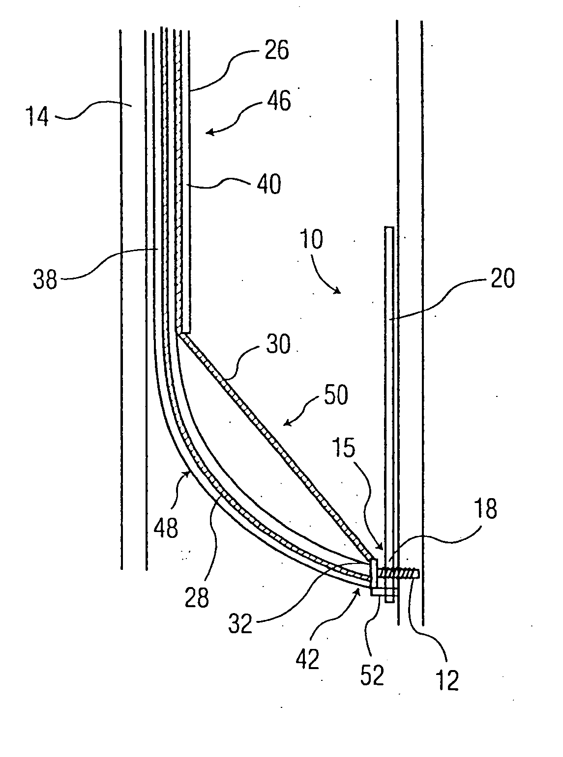
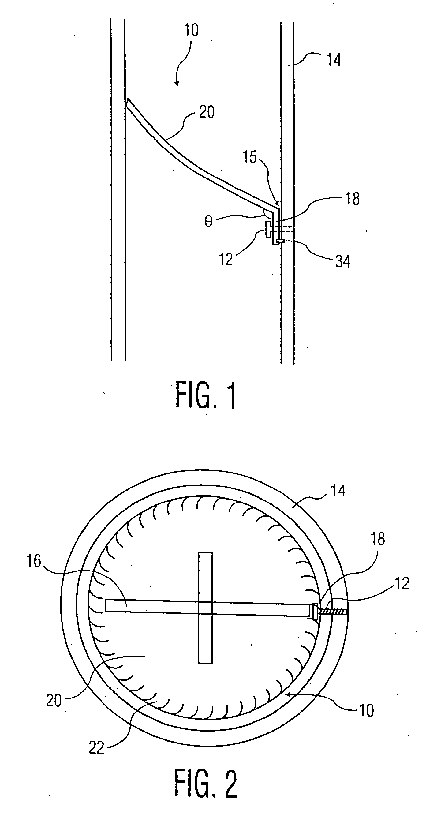
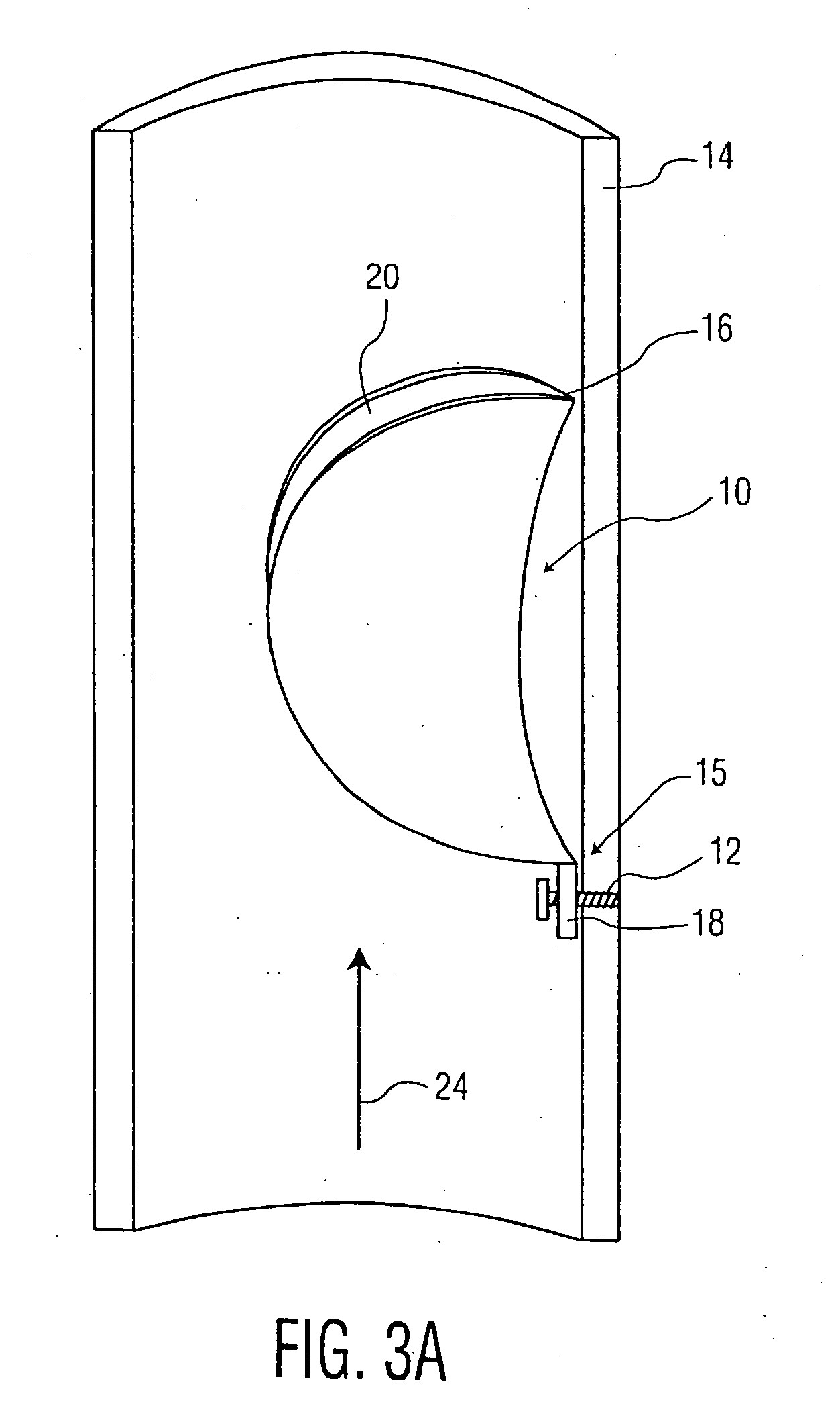
[0037]FIG. 1 illustrates a valve, identified generally as 10. In a preferred embodiment, the valve 10 is a venous valve for placement within a vein. The valve 10 can include a valve element 20 and a base 18, where the valve element or leaflet 20 is connected to the base 18 by a movable joint such as a hinge 15.

[0038] The valve 10 can be attached within a vessel having a vessel wall 14. The valve 10 can be attached to the vessel wall 14 by a tissue connector 12 which can include a pin, a screw or a staple, for example. The connector 12 can connect the valve 10 by its base 18 to the vessel wall 14. When the connector 12 is placed into the vessel wall 14, only a small portion of the connector 12 contacts the endothelium of the vessel wall 14 and the blood within the vessel. With such a configuration of the connector 12, there is less trauma to the wall 14 compared to the use of a stent, for example.

[0039] The valve 10 can also include a second connector 34. The second connector 34 ca...


PUM


Abstract

An implantable valve having a valve element or leaflet and a base that is attachable to a vessel wall using a connector such as a screw, pin or a staple. The valve can be implanted using a catheter to position the valve in a desired location and drive the connector into the vessel wall. The valve can be used as a venous valve to control blood flow within the veins, arteries, heart or the aorta of a patient.

Description

CROSS-REFERENCE TO RELATED APPLICATIONS [0001] This application is a continuation of U.S. application Ser. No. 10 / 401,210, filed Mar. 27, 2003, which is a divisional application of U.S. application Ser. No. 09 / 697,094, filed Oct. 26, 2000 now U.S. Pat. No. 6,602,286, the specification of which is incorporated herein by reference.BACKGROUND OF THE INVENTION [0002] Venous valves can improve the severe symptoms of patients with post thrombotic syndrome suffering from swelling and ulcerations of their legs. This condition can be caused by stenosis and occlusions of the veins and deterioration of the venous valves. Certain techniques have been developed to surgically restore incompetent valves or to implant devices that aid in such restoration. However, there remain many situations in which a valve is compromised to the extent that these options are not effective and valve replacement must be considered. By replacement of the venous valves, the capillary venous pressure can be decreased ...

Claims


Application Information

Patent Timeline
Patent Type & Authority Applications(United States)
IPC IPC(8): A61F2/06A61B17/00A61B17/064A61F2/02A61F2/24
CPCA61B17/064A61B2017/00783A61B2017/0647A61F2/2412A61F2/2475A61F2220/0016
Inventor STRECKER, ERNST PETER
Owner BOSTON SCI SCIMED INC
Why Eureka
Try Eureka