
Bag filter supporting cage member for a bag filter system, as well as method for producing the same

Inactive Publication Date: 2007-05-31
SCHEUCH GMBH
View PDF7 Cites 10 Cited by
  • Summary
  • Abstract
  • Description
  • Claims
  • Application Information

AI Technical Summary

Benefits of technology

[0007] It is now an object of the invention to provide a remedy for this situation and to propose a new construction of a bag filter supporting cage member as well as an appropriate method of production for the supporting cage member and an associated arrangement, wherein the supporting cage, optionally also a cage portion which is put together with other ones, can be finished on the location of assembly and use of the filter systems in a simple manner from the rings and rods, so that the production is simplified and, more-over, the problem of transportation is solved since merely longitudinal rods and rings, i.e. elements which are compact to package, are to be transported.
[0011] As has already been mentioned, known supporting cages have to be prefabricated in production plants far from the bag filter systems to be set up and then have to be transported to the location of the bag filter systems. For this transportation, the supporting cages usually are accommodated in wooden crates or in special transport baskets. The packages have heights of up to 1.5 m, and several layers of supporting cages may be stored one on top of the other. Then the weight of, e.g., 9 layers of supporting cages, will rest on the lowermost supporting cage layer. Impact loads occurring during loading and unloading and during the transportation itself necessarily will result in a certain percentage of damage. Likewise, manipulations carried out during packing and unpacking will cause damage. With a view to extended storage times and longer routes of transportation, e.g. in case of transportation by ship, it is necessary to coat the supporting cages with a corrosion protection means, with galvanizing treatments or also a varnish coating being commonly used, apart from the fact that the supporting cages possibly have to be packed in sea chests. The high costs for packing and transportation involved therein just as the risk of a damage occurring during handling and during transportation and, possibly, the corrosion protection which mostly is not necessary for the operation in the bag filter system can be avoided by applying the technique according to the invention: a corrosion-protected semi-finished product (galvanized or copper-plated rods and rings, respectively) are delivered in compact packing units, and on location the supporting cage members or cages are assembled from the semi-finished products, shortly before the time of their installation. These semi-finished products can also be packaged at low costs in corrosion-protected manner in that it is shrink-wrapped so that—unless required for the operation of the bag filter system—the application of a corrosion protection in form of galvanizing or copper-plating can be omitted. The packaging expenditures for the transportation of the said semi-finished products are low so that the transportation will become extremely cost-effective. The packaging density (e.g. in kg / m3) increases in this manner to the twenty-fold, e.g., in comparison with supporting cages according to the prior art. Also this will result in substantially lower packaging and shipping costs. Furthermore, any risk of damage occurring during packing, transportation and unpacking is practically eliminated, since only handling of rods and rings, yet not of bulky, comparatively fragile supporting cages is required. Due to the fact that they will be assembled only after their transportation, the supporting cages can be made of longitudinal rods and rings of comparatively slight cross-sectional dimensions, since the aforementioned load thereon during transportation is omitted.
[0012] In the known supporting cages which in their finished state have to be transported to the location of the bag filter system to be set up, the cages must not damage each other when being transported, when supporting cages arranged on top weigh down on the supporting cages below them during impact loads. Therefore, a more massive construction with larger cross-sectional dimensions of the rings and longitudinal rods is required for the transportation of the supporting cages than would actually be needed for the filtering operation proper, e.g. longitudinal rods having a diameter of 3 mm would suffice for the filtering operation, yet with the known supporting cages, rod diameters of 4 mm are required because of the mechanical loads occurring during their transportation. The supporting cage according to the invention with its special connecting technique allows for a production on location, and therefore—since no transportation-caused damage of finished supporting cages need be feared—a more light-weight production, e.g. with the said rod diameters of 3 mm, can be realized.

Problems solved by technology

What is disadvantageous with this known construction is that when producing the welding connections between the longitudinal rods and the rings, exact positioning is required, wherein as a rule, the straightness of the longitudinal rods is negatively affected if the positioning is not quite exact.
The longitudinal rods may also become warped due to the heat introduced during welding.
A further disadvantage is that the longitudinal rods and the rings usually are made of a round material of galvanized steel, wherein during welding, the surface protection becomes damaged at the welds and adjacent the same so that the supporting cage must be galvanized again after it has been produced.
However, this production of supporting cage members of plastics also is complex, even though exact positioning of longitudinal rods is omitted.
Besides, the strength of the supporting cages is not as good as desired.
What is disadvantageous with these known supporting cage constructions—as with all the other known supporting cages—in particular is also that the supporting cages for filter systems to be set up, because of the relatively complicated production (spot welding or injection molding) must at first be centrally produced and then they must be transported to the location of the filter system; however, the supporting cages or cage portions are bulky structures, resulting in large transport volumes—with much “air”.

Method used


Image

  • Bag filter supporting cage member for a bag filter system, as well as method for producing the same
  • Bag filter supporting cage member for a bag filter system, as well as method for producing the same
  • Bag filter supporting cage member for a bag filter system, as well as method for producing the same

Examples


Embodiment Construction

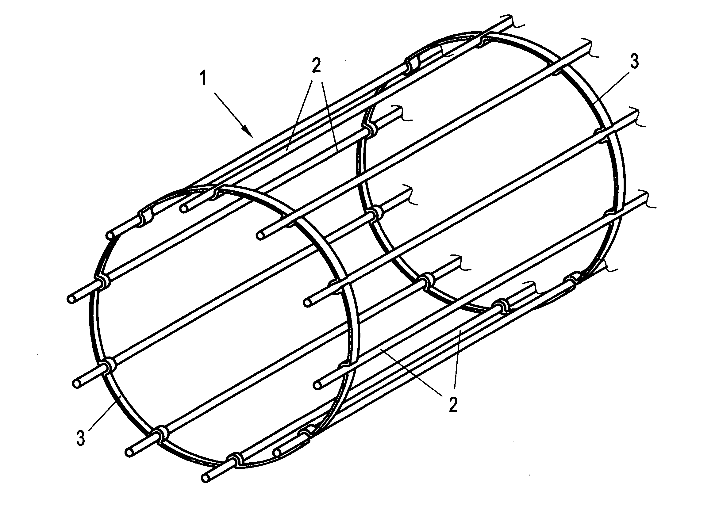
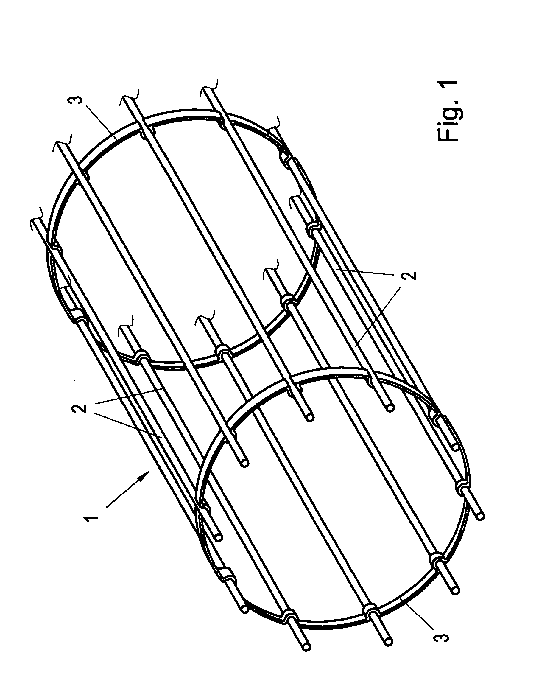
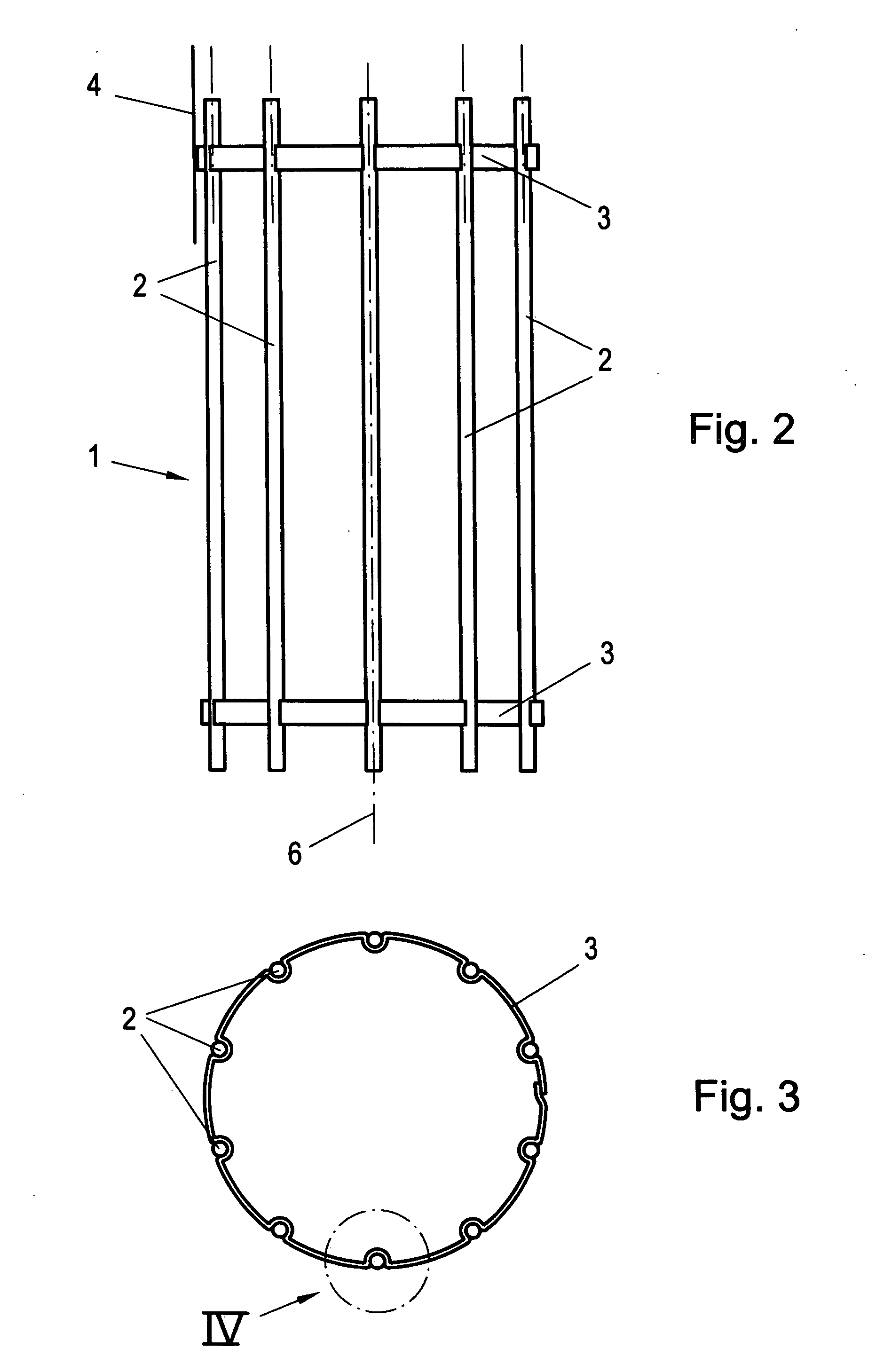
[0027] In FIG. 1, a section or part of a bag filter supporting cage or cage member 1 is shown in perspective, which is assembled of longitudinal rods 2 arranged parallel to each other, and (connecting) rings 3 arranged with the ring planes transversely to the longitudinal rods 2. On such supporting cages 1, bag filters are pulled up for the operation in bag filter systems, and in FIG. 2 (as also in FIG. 9) in a partial region such a bag filter 4 is indicated only quite schematically.

[0028] In detail, the rings 3 according to FIGS. 1 to 9 consist of a flat material, strip material or the like, having a width (height) of 10 mm, e.g.. These rings have axis-parallel groove-like receiving depressions 5 distributed over their peripheries, termed grooves 5 in short hereinafter, which grooves, e.g. in case that metal flat materials are used for the rings 3, are shaped by bending, pressing or embossing of the rings 3, cf. also FIGS. 7 and 8 in addition to FIGS. 5 and 6. These axis-parallel ...


PUM

PropertyMeasurementUnit
Angleaaaaaaaaaa
Angleaaaaaaaaaa
Deformation enthalpyaaaaaaaaaa

Abstract

A bag filter supporting cage member for a bag filter system, includes several longitudinal rods which are connected to mutually spaced-apart rings, wherein the rings have groove-like receiving depressions which are open towards the outer side, the longitudinal rods being received and held therein.

Description

FIELD OF THE INVENTION [0001] The invention relates to a bag filter supporting cage member for a bag filter system, said cage member comprising several longitudinal rods connected to mutually spaced-apart rings. [0002] Furthermore, the invention relates to a method of producing such a cage member. BACKGROUND OF INVENTION [0003] Bag filter systems for filtering air or the like gases loaded with particles are known e.g. from documents DE 19 944 057 A, DE 32 27 712 A, U.S. Pat. No. 3,747,307 A or U.S. Pat. No. 5,173,098 A. There, relatively long bag filters (e.g. having a length of 6 m) made of an air-permeable fabric or the like material which, however, retains the particles, are arranged externally of an inner supporting cage, and these bag filters are fastened in a closed filter enclosure; the air to be purified is supplied to the interior of the enclosure, whereas the interior of the bag filters is subjected to negative pressure via a suction device. In this manner, the air is suck...

Claims


Application Information

Patent Timeline
IPC IPC(8): B01D46/00
CPCB01D46/0001B01D46/02B01D46/06B01D2265/06
Inventor FLISZAR, ING. GUNTHER
Owner SCHEUCH GMBH
Learn More