

Substrate processing apparatus and substrate processing method
a substrate processing and substrate technology, applied in the direction of electrical equipment, chemistry equipment and processes, cleaning processes and apparatuses, etc., can solve the problems of processing defects on the substrate w, and achieve the effect of preventing processing defects on the substrate and reducing throughpu
- Summary
- Abstract
- Description
- Claims
- Application Information
AI Technical Summary
Benefits of technology
Problems solved by technology
Method used
Image

Examples
first embodiment
1. First Embodiment
[0117] (1) Structure of Substrate Processing Apparatus
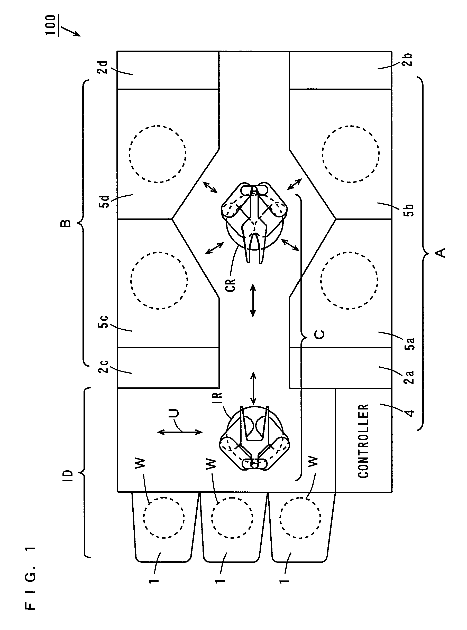
[0118]FIG. 1 is a plan view of a substrate processing apparatus according to a first embodiment. As shown in FIG. 1, the substrate processing apparatus 100 has processing regions A, B, and a transporting region C between the regions A, B.
[0119] The processing region A includes a controller 4, fluid boxes 2a, 2b, and cleaning processing units 5a, 5b.
[0120] The fluid boxes 2a, 2b shown in FIG. 1 respectively house fluid related equipment such as pipes, joints, valves, flow meters, regulators, pumps, temperature controllers and process solution storage tanks involved in supply of the chemical solution or drain (discharge) of the rinse liquid to / from the cleaning processing units 5a, 5b.
[0121] Each of the cleaning processing units 5a, 5b performs a cleaning process using a chemical solution (hereinafter, referred to as chemical solution process) and a cleaning process using a rinse liquid (hereinafter, referred...
second embodiment
2. Second Embodiment
[0293] A substrate processing apparatus according to the second embodiment differs in structure from the substrate processing apparatus 100 according to the first embodiment in the following points.
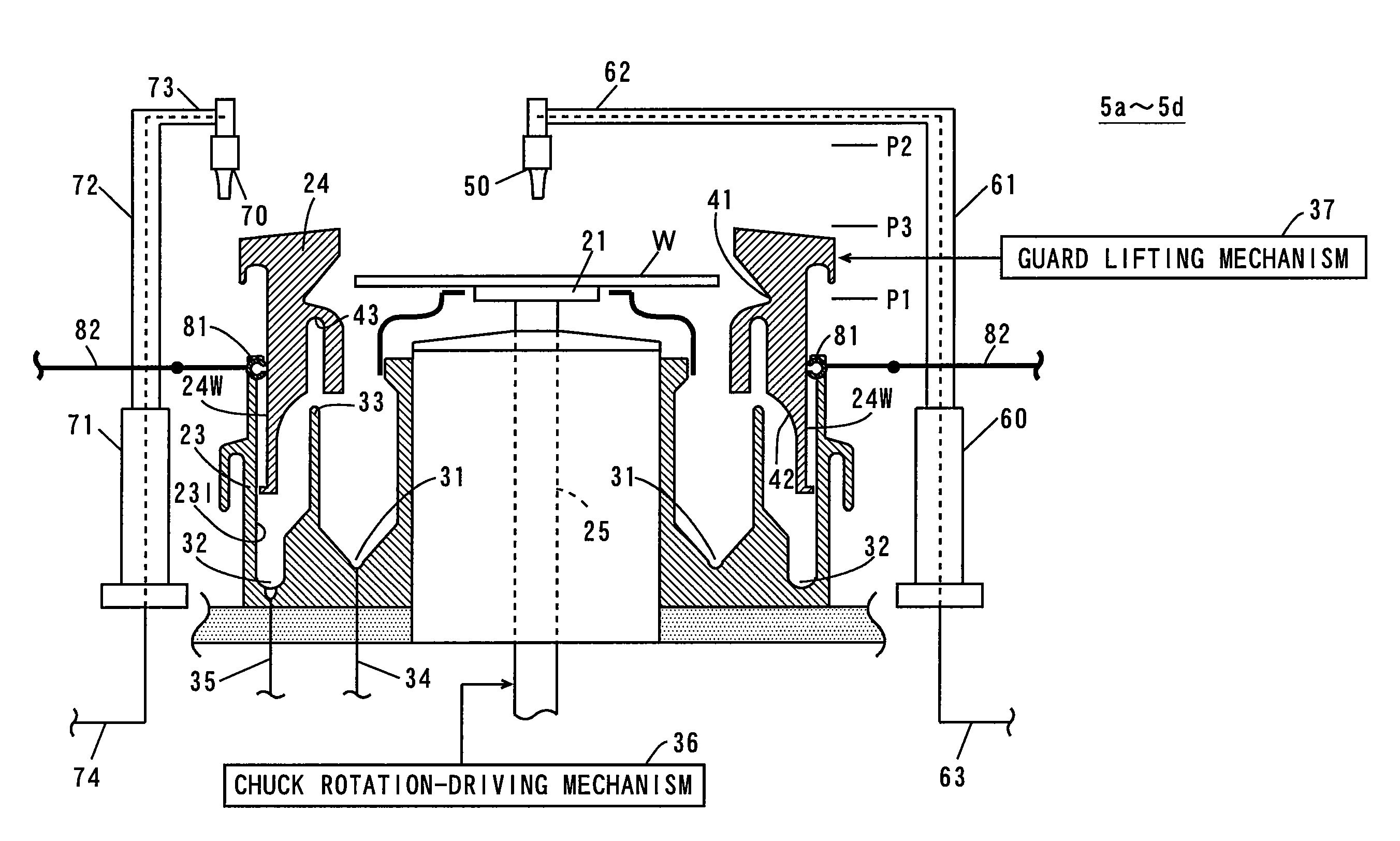
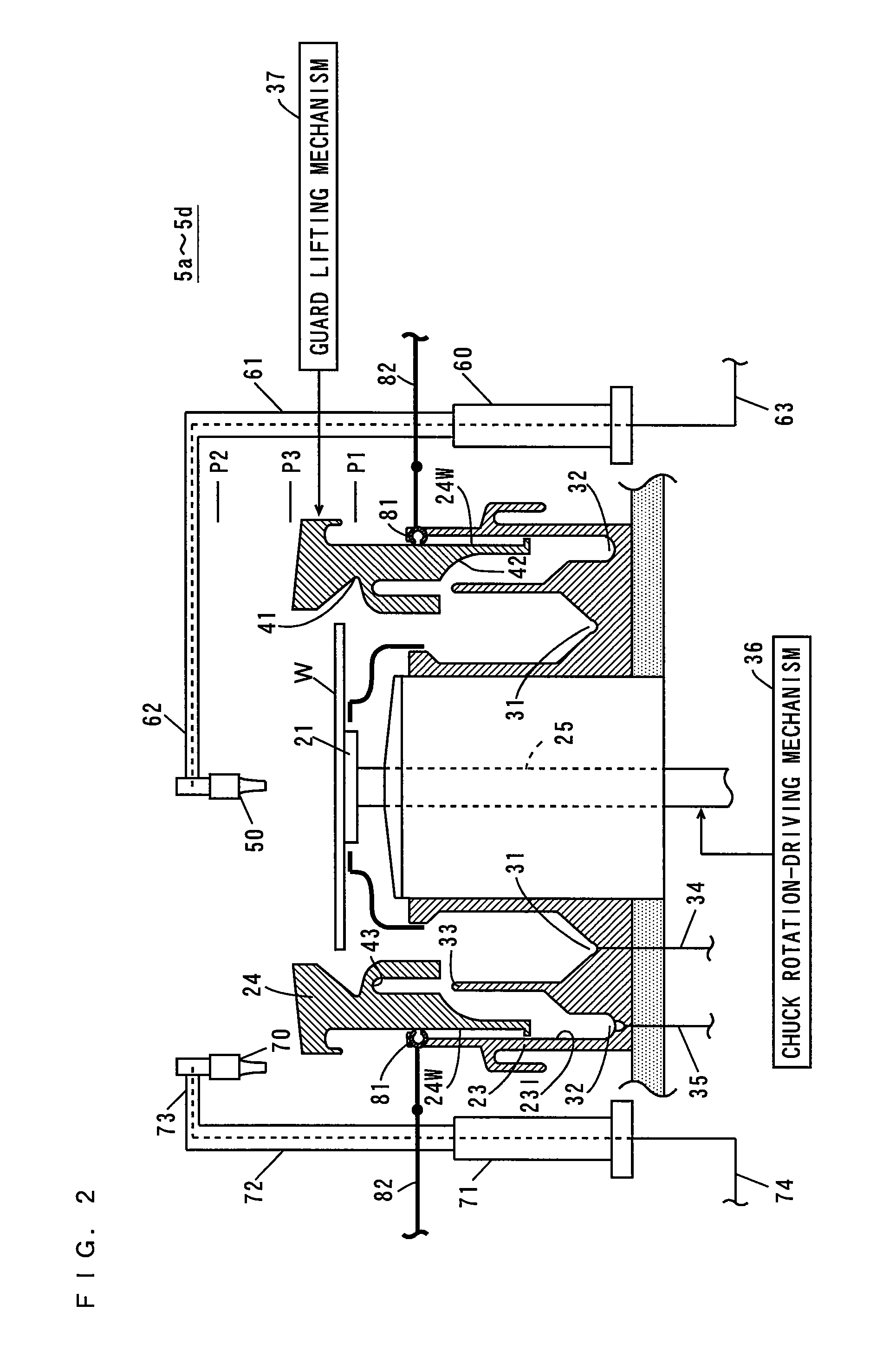
[0294] The substrate processing apparatus according to the present embodiment has a structure for removing precipitates of the chemical solution adhering to the recovery liquid guiding part 42 of the splash guard 24, or to the inner wall face 23I of the processing cup 23 in the cleaning processing unit 5a-5d shown in FIG. 2.
[0295]FIG. 14 is a view for explaining the structure of the cleaning processing unit 5a-5d in the substrate processing apparatus according to the second embodiment.
[0296] As shown in FIG. 14, in the present embodiment, in place of the guard cleaning nozzles 81 shown in FIG. 2 provided on the upper end of the processing cup 23 in the first embodiment, member cleaning nozzles 91 are attached to the upper end of the partition wall 33. The member cle...
third embodiment
3. Third Embodiment
[0314] A substrate processing apparatus according to the third embodiment differs in structure from the substrate processing apparatus 100 according to the first embodiment in the following points.
[0315] The substrate processing apparatus according to the present embodiment has structure for removing precipitates of the chemical solution adhering to the vicinity of the lower end of the inner wall face 23I of the processing cup 23 in the cleaning processing unit 5a-5d shown in FIG. 2.
[0316]FIG. 16 is a view for explaining the structure of the cleaning processing unit 5a-5d in the substrate processing apparatus according to the third embodiment.
[0317] As shown in FIG. 16, in the present embodiment, in place of the guard cleaning nozzles 81 shown in FIG. 2 provided on the upper end of the processing cup 23 in the first embodiment, member cleaning nozzles 93 are attached to the vicinity of the lower end of the partition wall 33. The member cleaning nozzles 93 have ...
PUM
| Property | Measurement | Unit |
|---|---|---|
| outer diameter | aaaaa | aaaaa |
| outer diameter DC | aaaaa | aaaaa |
| hole diameter | aaaaa | aaaaa |
Abstract
Description
Claims
Application Information