
Dispensing system and method for shower arm

a technology of shower arm and dispenser, which is applied in the direction of instruments, combustion types, separation processes, etc., can solve the problems of difficult connection of such systems, difficulty in refilling such systems, and cluttered showers, and achieves simple and fast manual operation, simple operation, and convenient rotation

Active Publication Date: 2007-05-31
WATER PIK INC
View PDF99 Cites 40 Cited by
  • Summary
  • Abstract
  • Description
  • Claims
  • Application Information

AI Technical Summary

Benefits of technology

[0008] In one embodiment, the flask (and flexible container held within the flask) are connected in fluid-pressure communication with the first tube member, through an extension portion and a second tube member, where the second tube member and the extension portion are coupled to the first tube member, so as to be rotatable around the longitudinal axis of the first tube member (rotatable about the fluid flow passage through the first tube member). As a result, the flask may be readily rotated to a convenient position relative to the first tube member, such as below the first tube member, after the first tube member is installed in a fixed position to an existing standard pipe of a shower arm (or to a fluid conduit of another type of fluid-flow system).
[0009] In a further embodiment, a connection structure is provided for allowing the flask to be connected to the extension portion for operation, but selectively releasable from the extension portion by a user. A quick-release connection structure may be employed, to allow a user to selectively connect and release the flask, with a simple and fast manual operation (preferably an operation that requires only one hand of the user). In that manner, a user may quickly exchange one flask for another or replace a flask having an empty container with another flask, in a simple operation. A group or family sharing a shower facility may have two or more flasks, such that each family or group member (or sub-group) may have a corresponding flask and be able to easily exchange one flask for his or her corresponding flask, when using the shower facility.
[0010] In a further embodiment, the flexible container held within the flask may be secured to the flask cover by a connection structure that has mating members on the container and on the flask cover. The mating members may include one or more protrusions and mating grooves and / or non-circular mating shapes, such that only a flexible container having the correct configuration of one or more protrusions and grooves and / or mating shape may be coupled to a particular flask cover. By selecting a configuration of one or more protrusions and grooves and / or mating shape, a user or manufacturer may provide a level of control regarding which flexible container (and, thus, which material contained in the flexible container) may be operatively connected to a given flask.

Problems solved by technology

The bottles and other containers tend to collect inside of the shower stall, resulting in possible safety and health problems, as well as causing the shower to appear cluttered.
It is believed that one reason for the lack of popularity of such previous dispensing systems is the difficulty of refilling such systems and of connecting such systems without changing the orientation or operation of the shower head or dispensing system.
Another reason is that regulatory restrictions placed on the maximum flowrate of water through a showerhead has introduced flow controllers into the showerheads that raise the water pressure in the shower arm to a level where it is difficult for a conventional venturi system to work effectively.

Method used


Image

  • Dispensing system and method for shower arm
  • Dispensing system and method for shower arm
  • Dispensing system and method for shower arm

Examples


Embodiment Construction

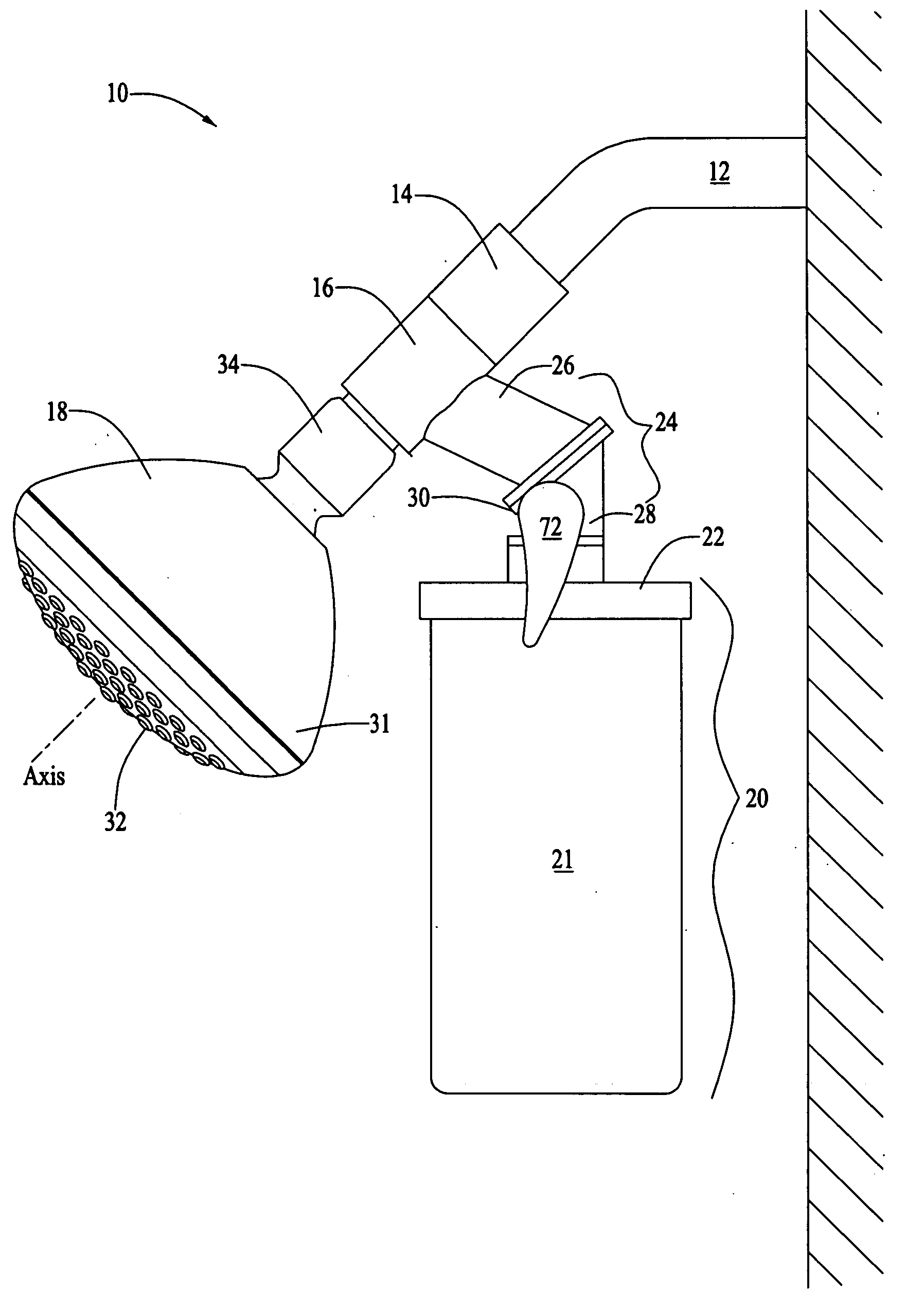
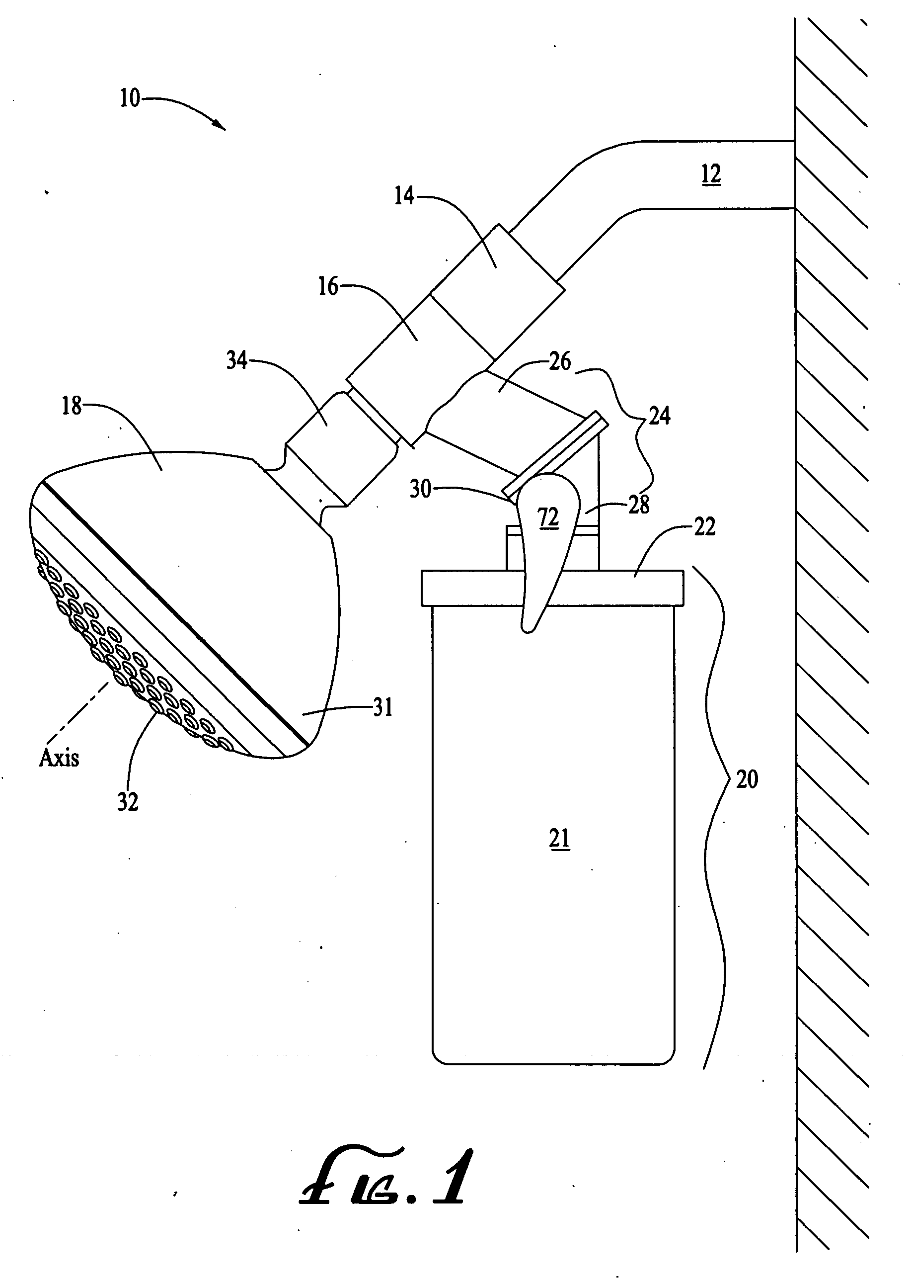
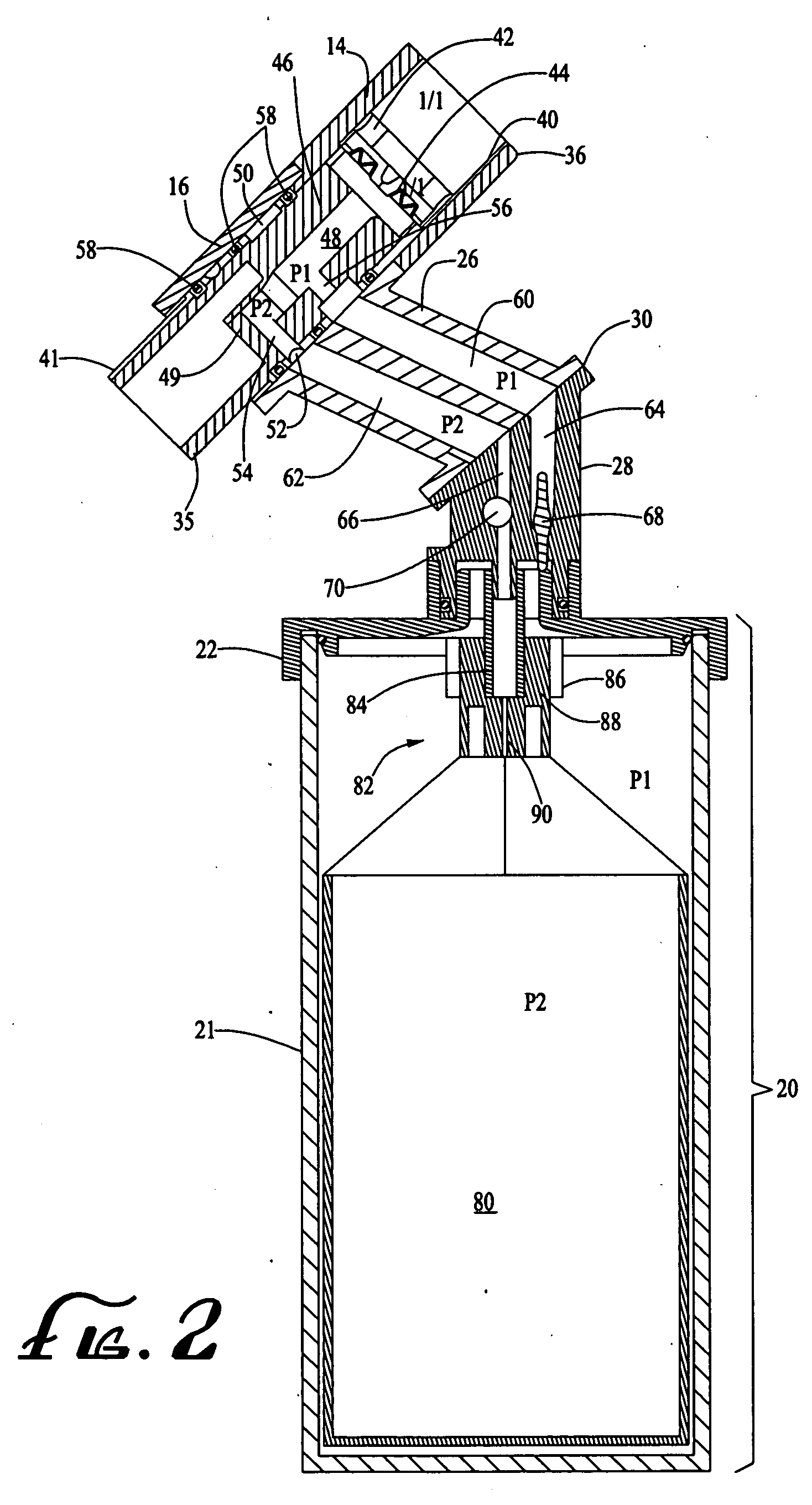
[0024] The present invention relates to dispensing systems for dispensing one or more materials into a fluid flow conduit, during the conveyance of fluid through the conduit. Further embodiments relate to components of such systems and methods of making and using such systems and components.

[0025] In one example embodiment, a dispensing unit is configured to connect to a standard pipe of a shower arm. The dispensing unit may be configured to dispense one or more hair shampoo, hair conditioner, soap, skin conditioner, moisturizer, medications, perfume, or other suitable materials or combinations thereof into a water flow in the shower arm. While embodiments of the present invention are described herein in the context of a shower facility having a conventional standard pipe of a shower arm that conveys water to a shower head, dispensing units according to other embodiments of the present invention may be configured to connect to other water flow pipes, hoses, supply elbows or other f...


PUM


Abstract

Dispensing systems for dispensing one or more materials into a fluid flow conduit, during the conveyance of fluid through the conduit are configured to connect to a fluid conduit, such as a standard pipe of a shower arm and dispense a material into the water flow in the shower arm. The system includes a first tube member having a restrictor flow passage to provide a pressure differential, as fluid flows through the tube member. The pressure differential created within the restrictor passage by the fluid flow is communicated to a flask, to provide a pressure differential between the interior and the exterior of a flexible container within the flask. The pressure differential causes material within the flexible container to be drawn out and conveyed to the fluid flowing through the tube member. The flask may be connected to the first tube member, through an extension portion that is rotatable around the first tube member for convenient positioning. A quick-release connection structure may allow the flask to be connected and selectively releasable from the system.

Description

CROSS-REFERENCE TO RELATED PATENT APPLICATIONS FIELD OF THE INVENTION [0001] The present invention relates to dispensing systems for dispensing one or more materials into a fluid flow conduit, during the conveyance of fluid through the conduit. Further embodiments relate to components of such systems and methods of making and using such systems and components. In one example embodiment, a dispensing unit is configured to connect to a standard pipe of a shower arm for dispensing one or more materials into a stream of water flowing through the shower arm. The dispensing unit may be configured to dispense one or more hair shampoo, hair conditioner, soap, skin conditioner, moisturizer, perfume, or other suitable materials or combinations thereof into the water flow in the shower arm. BACKGROUND OF THE INVENTION [0002] Modern household showers are provided with one or more standard pipe shower arms connected to the household water plumbing system. A shower head is typically attached to t...

Claims


Application Information

Patent Timeline
Patent Type & Authority Applications(United States)
IPC IPC(8): A62C13/62F23D14/28B05B7/04A62C13/66B05B7/32B67D7/78
CPCA62C13/00E03C1/046Y10T137/2526
Inventor SOMERFIELD, ALAN DAVIDSANDUSKY, THOMAS
Owner WATER PIK INC
Features
  • Generate Ideas
  • Intellectual Property
  • Life Sciences
  • Materials
  • Tech Scout
  • Unparalleled Data Quality
  • Higher Quality Content
  • 60% Fewer Hallucinations
Learn More