System, method, and apparatus for production-worthy, low cost composite tool fabrication

a composite tool and low cost technology, applied in the field of composite tooling, can solve the problems of high material and labor costs, impede production use, and lack of typical composite tooling, and achieve the effects of reducing labor costs, reducing cost, and eliminating autoclave tim

Active Publication Date: 2007-05-31
LOCKHEED MARTIN CORP
View PDF6 Cites 21 Cited by
  • Summary
  • Abstract
  • Description
  • Claims
  • Application Information

AI Technical Summary

Benefits of technology

[0007] One embodiment of a system, method, and apparatus for fabricating composite tooling resolves the above-mentioned deficiencies using various embodiments and materials. For example, low cost dry fabrics and a neat BMI resin may be used instead of expensive prepregs. Labor is also notably reduced since dry fabrics conform much more readily to contours than do prepregs. In addition, autoclave time is eliminated since the process simply utilizes vacuum-assisted resin infusion and an oven. Tooling constructed in accordance with the present invention also may utilize a high temperature surface coating that is filled with ceramic particulate (80% loading). This provides a tool surface with greatly enhanced abrasion and damage resistance, and vacuum integrity is assured since there are no fiber-induced leak paths at or near the tool surface.
[0008] In one embodiment, the present invention places dry, three-dimensional (3D) woven pi-shaped preforms on the dry tool substrate, followed by installation of pre-cured, pre-cut “eggcrate” planks, which are then tied together with additional dry, pi-shaped preforms. Finally, the entire assembly is infused and cured together to form a high strength, unitized tool. Imprecise and expensive hand wet-out and lay-up of tie plies for attachment of egg crate planks to the substrate is eliminated. The present invention also provides tight control of resin content and distribution with vacuum infusion. This process eliminates the primary cause of structural weakness and tool distortion, which typically occurs at the attachment interface when traditional methods are used. The pi-shaped preforms additionally provide much greater pull off strengths at that interface than do hand-laid tie plies.
[0010] From a structural and durability standpoint, the solution presented herein makes notable improvements in the two weakest aspects of composite tooling, namely, the substrate-to-egg crate interface, and the durability of the tool surface. These two improvements increase the service life of BMI tools, thereby reducing production life cycle costs even further. In terms of acquisition cost, this solution allows BMI tooling to compete cost wise with metallic tooling. BMI tools built with these concepts offer all the inherent advantages of composite tooling, while eliminating the traditional disadvantages of high cost and poor durability.

Problems solved by technology

However, typical composite tooling also has deficiencies which, in many cases, preclude its use for production.
These deficiencies include high material and labor costs, such as those for prepregs, protracted lay-up time, long autoclave compaction and cure cycles.
Composite tooling also exhibits poor surface durability and / or vacuum integrity since polymeric surfaces do not last long in a production environment.
In addition, composite tooling typically uses archaic and expensive methods to attach an “egg crate” type structural support to the tool substrates.
It also has inherent weakness in the substrate-to-egg crate attachment schemes (e.g., the tool dimensional stability erodes over time).
Moreover, an intermediate tool fabrication step is usually required since machined master models cannot hold tolerances when subjected to elevated cure temperatures.
This adds significant cost to the final product, and increases the risk of dimensional tolerance build-up.
Furthermore, there is degradation of tool laminates due to thermal cycling since epoxy tools cannot handle much more than 100 cycles.
The move by some in the industry toward prepreg BMI tools has done nothing to address the exorbitant acquisition costs of prepreg tooling, or their susceptibility to both surface and substructure damage.
This can be true even when factoring the higher cost of handling heavy INVAR tools, their inefficient heat up and cool down rates, and their dimensional inaccuracies and / or instability.

Method used


Image

  • System, method, and apparatus for production-worthy, low cost composite tool fabrication
  • System, method, and apparatus for production-worthy, low cost composite tool fabrication
  • System, method, and apparatus for production-worthy, low cost composite tool fabrication

Examples


Embodiment Construction

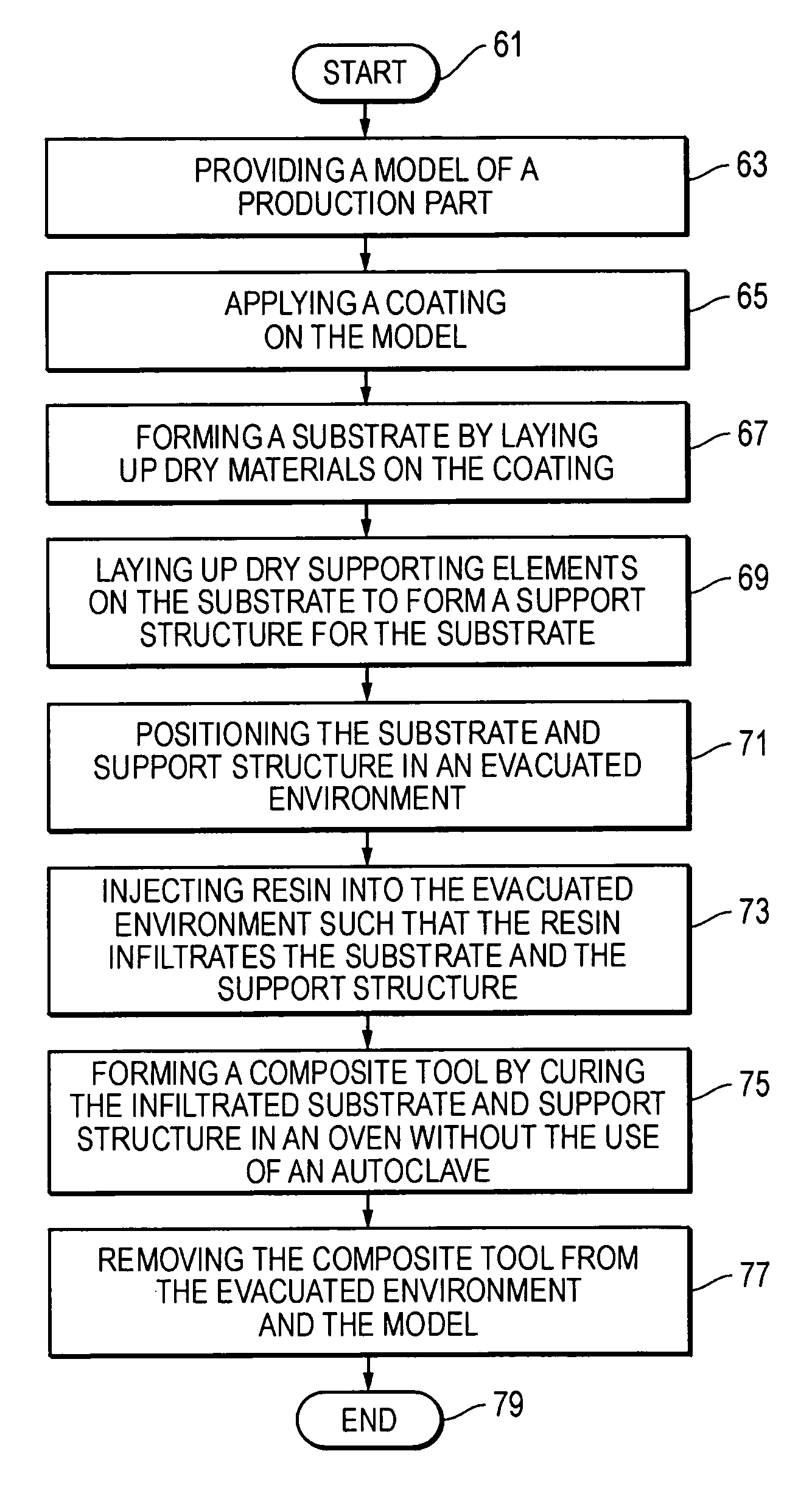
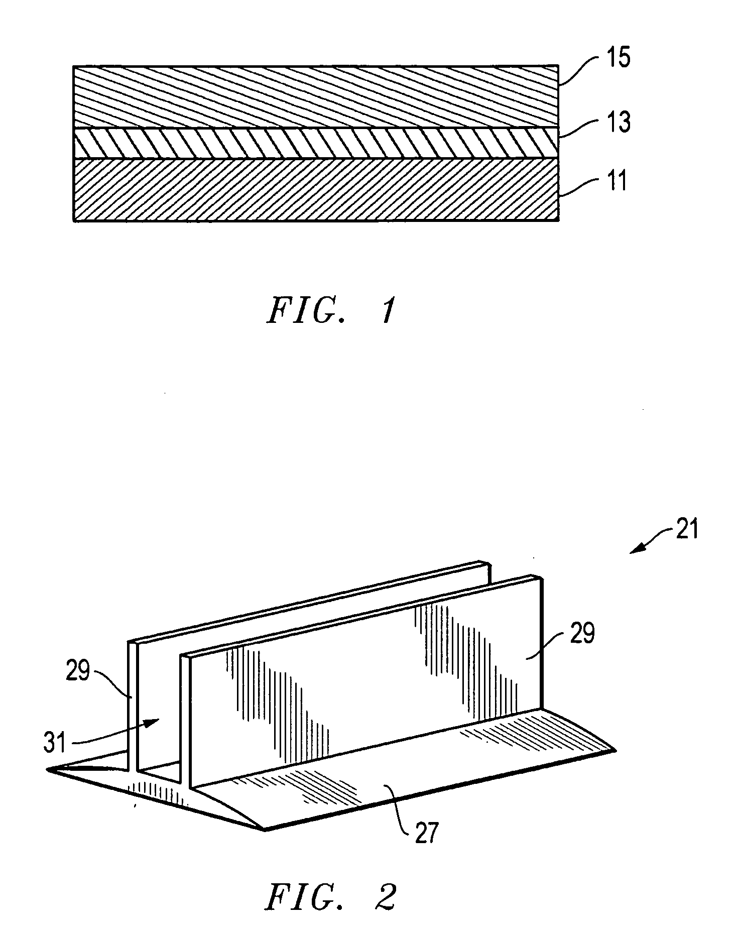
[0019] Referring to FIGS. 1-6, various embodiments of forming composite tooling are disclosed. In one embodiment, the method includes providing a model 11 (FIG. 1) of a production part. A ceramic-filled face coating 13 is applied to the contact surface of the model 11 in a liquid form. When cured, the coating 13 has a hardness that exceeds that of a substrate 15 that ultimately forms the composite tool. In one embodiment, the substrate 15 is formed by laying up dry materials, such as woven graphite, on the coating 13. These materials are substantially dry and are not pre-impregnated with resin or the like.

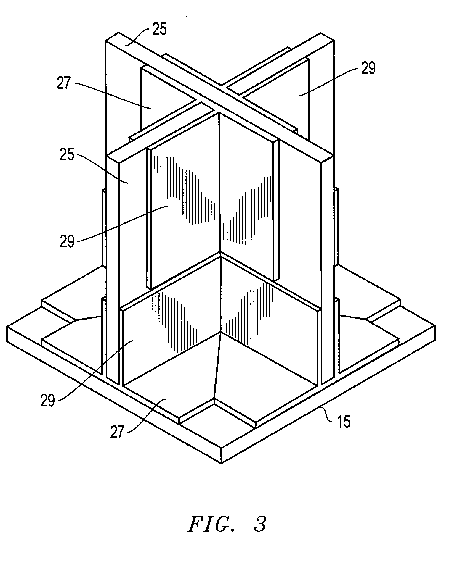
[0020] In a subsequent step, dry supporting elements 21 are laid up on the substrate 15 to form a support structure 23 (see FIG. 4) for the substrate 15. Like the dry materials of substrate 15, the dry supporting elements 21 are substantially dry and are not pre-impregnated. These designs are more fully disclosed in U.S. Pat. Nos. 6,374,570 and 6,520,706, which are incorporated he...


PUM

PropertyMeasurementUnit
depthaaaaaaaaaa
temperatureaaaaaaaaaa
temperaturesaaaaaaaaaa

Abstract

Composite tooling is fabricated with low cost dry fabrics and a neat resin instead of expensive prepregs. Dry, three-dimensional woven joint preforms are placed on a dry tool substrate and dry, 3D preforms are also placed between pre-cured egg crate-like junctions. The entire tool substrate and substrate-to-support structure joints are then resin-infused simultaneously through the use of rota-molded tooling aids, providing an additional reduction in cost. Tight control of resin content and distribution with vacuum infusion is thereby provided. This process eliminates the primary cause of structural weakness and cooling distortion, which typically occur at the attachment interface when existing methods are used. The preforms provide significantly greater pull-off strengths at interfaces than do hand-laid tie plies. Issues with tool surface durability are addressed through the use of ceramic-filled face coat.

Description

BACKGROUND OF THE INVENTION [0001] 1. Technical Field [0002] The present invention relates in general to composite tooling and, in particular, to an improved system, method, and apparatus for improved, low cost composite tool fabrication of composite parts. [0003] 2. Description of the Related Art [0004] Composite carbon fiber tooling for fabrication and cure of composite parts has traditionally offered several advantages, including significantly lower weight, which facilitates ease of handling. If designed and fabricated properly, composite tooling can also provide precise match-up of a tool's coefficient of thermal expansion (CTE) to that of the part. In addition, composite tooling has a low thermal mass, such that heat up and cool down becomes much more efficient than that of metallic (e.g., INVAR) tooling. Moreover, composite tooling provides close replication of original master model dimensions and contours, and reduced acquisition lead time as compared to metallic tooling. [00...

Claims


Application Information

Patent Timeline
Patent Type & Authority Applications(United States)
IPC IPC(8): B29C70/36
CPCB29C33/3842B29C33/40B29C70/443
Inventor ASHTON, TODD H.BATZER, RICHARD R.SCHMIDT, RONALD P.
Owner LOCKHEED MARTIN CORP
Why Eureka
Try Eureka