Display apparatus
a display apparatus and display technology, applied in the direction of discharge tube luminescnet screens, discharge tube/lamp details, electric discharge lamps, etc., can solve the problems of non-luminescent area, deterioration of display qualities, and inability to supply constant power potential to the entire display area, so as to reduce potential fluctuation, alleviate deterioration of display quality, and increase the frame area of display apparatus
- Summary
- Abstract
- Description
- Claims
- Application Information
AI Technical Summary
Benefits of technology
Problems solved by technology
Method used
Image
Examples
first embodiment
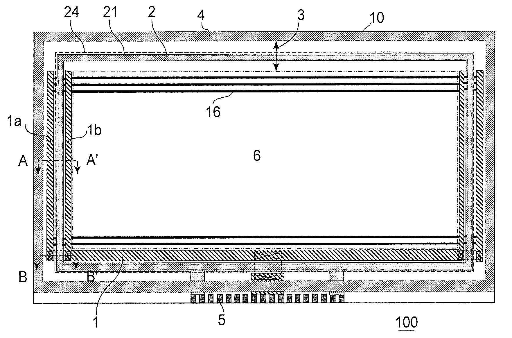
[0054]FIG. 3 is a schematic plan view of an organic EL display apparatus according to First Embodiment of the present invention.
[0055] Referring to FIG. 3, a display apparatus 100 includes a single substrate 10 having a substrate surface divided into a display area 6 (an area inside an inner dash-double-dot line) and a peripheral area (an area between the inner dash-double-dot line and an outer dash-double-dot line). In order to block an organic EL device from external air, in the case where the substrate surface is covered with a cap formed of glass or metal, an adhesion area 4 for causing the cap to adhere to the substrate surface is disposed outside the peripheral area 3.
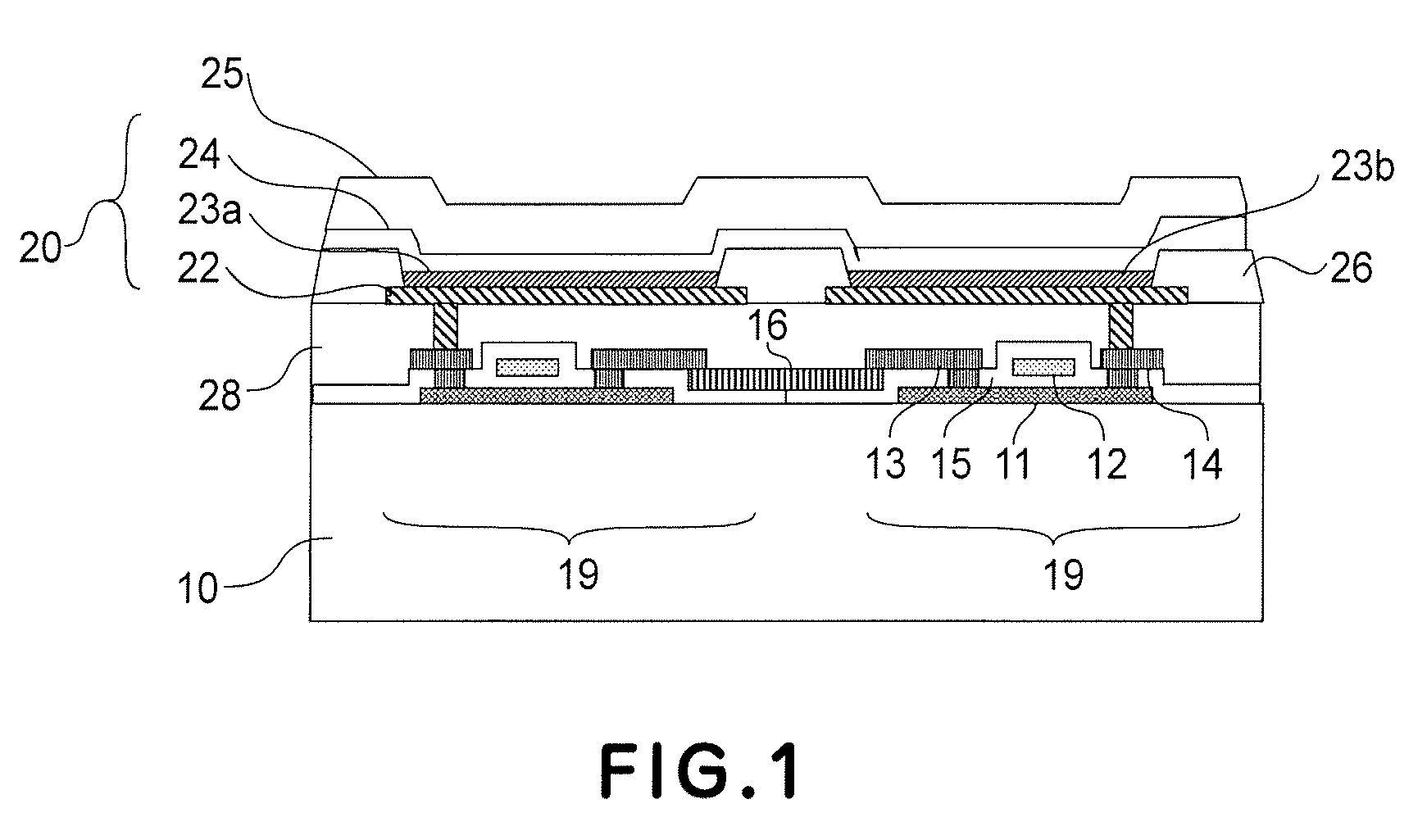
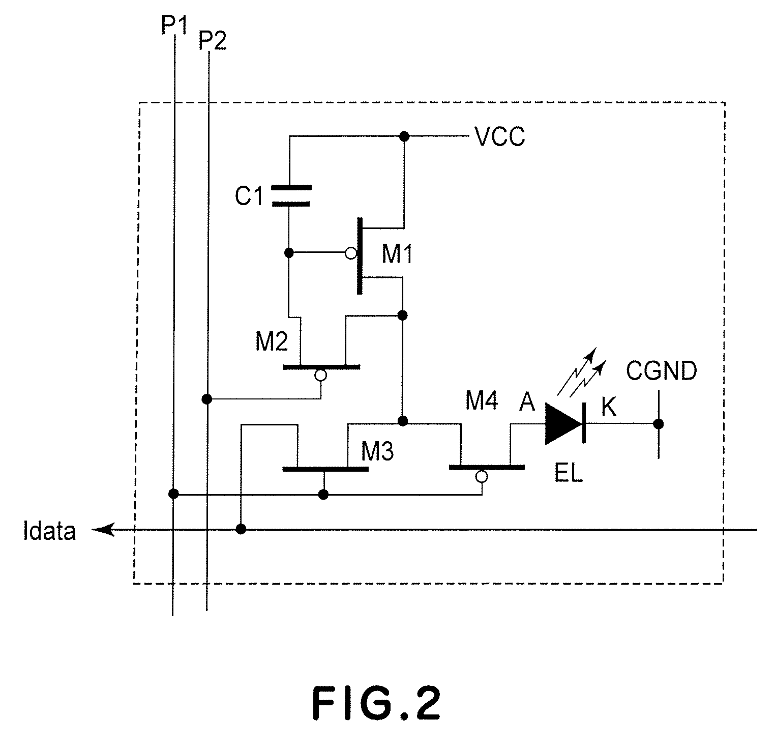
[0056] The display area 6 is an area in which the organic EL device 20 and the drive circuit 19 which are shown in FIG. 1 are arranged in a matrix. In this embodiment, the power lines 16 are disposed in a row direction and are parallel to gate signal lines. It is also possible to dispose the power lines 16 in a...
second embodiment
[0078]FIG. 6 is a schematic plan view showing a display apparatus according to Second Embodiment of the present invention, wherein members or portions identical to those in First Embodiment are represented by reference numerals identical to those in First Embodiment and wherein the EL device and the drive circuit in the display area are identical to those in First Embodiment.
[0079] A cross section taken along C-C′ line in FIG. 6 is shown in FIG. 7.
[0080] In First Embodiment, the power supply line 1 is divided into two lines but is a single line in this embodiment. The single power supply line 1 is disposed inside the common voltage line 21, i.e., on a side close to the display area 6, in parallel to the common voltage line 21.
[0081] The second electrode 24 and the common voltage line 21 do not directly contact each other but are oppositely disposed with another metal layer 29 as an interposed layer. This is because a contact resistance between the second electrode 24 and the comm...
PUM
 Abstract
Description
Claims
Application Information
 - R&D
- Intellectual Property
- Life Sciences
- Materials
- Tech Scout
- Unparalleled Data Quality
- Higher Quality Content
- 60% Fewer Hallucinations
Browse by: Latest US Patents, China's latest patents, Technical Efficacy Thesaurus, Application Domain, Technology Topic, Popular Technical Reports.
© 2025 PatSnap. All rights reserved.Legal|Privacy policy|Modern Slavery Act Transparency Statement|Sitemap|About US| Contact US: help@patsnap.com


