Holographic optical pickup apparatus

a technology of optical pickup and optical pickup, which is applied in the direction of recording/reproducing/erasing using optical interference patterns, instruments, data recording, etc., can solve the problems of increasing the cost of spatial light modulators, cmos sensors, or the like with the increase in size, and achieve the effect of reducing thickness and production costs

Inactive Publication Date: 2007-05-31
CANON KK
View PDF10 Cites 15 Cited by
  • Summary
  • Abstract
  • Description
  • Claims
  • Application Information

AI Technical Summary

Benefits of technology

[0030] It is, therefore, an object of the present invention to provide a holographic optical pickup apparatus which can be reduced in thickness and production cost while having a beam shaping means.
[0032] With such structure, a light beam incident on the spatial light modulator has an elliptical cross section which is smaller in diameter, so that the spatial light modulator can be reduced in size and cost.
[0033] Further, by adopting such disposition that the short-axis of the emitted light having the elliptical cross section is perpendicular to a surface of a medium, a spatial light modulator having a rectangular shape can be disposed such that a short side thereof is perpendicular to the surface of the medium, so that it is possible to reduce the thickness of a portion between the laser light source and the beam shaping means of the optical pickup apparatus.

Problems solved by technology

Further, there is also posed a problem that the spatial light modulator, the CMOS sensor, or the like is increased in cost with the increase in size thereof.

Method used


Image

  • Holographic optical pickup apparatus
  • Holographic optical pickup apparatus
  • Holographic optical pickup apparatus

Examples


embodiment 1

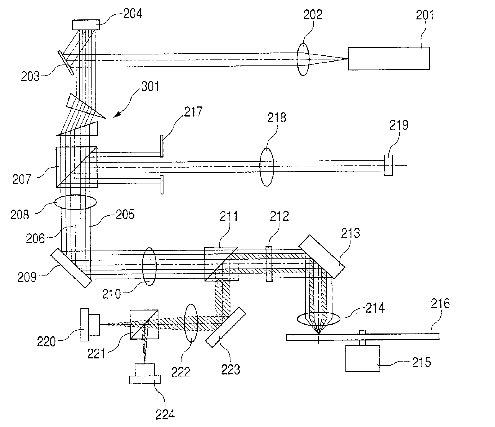
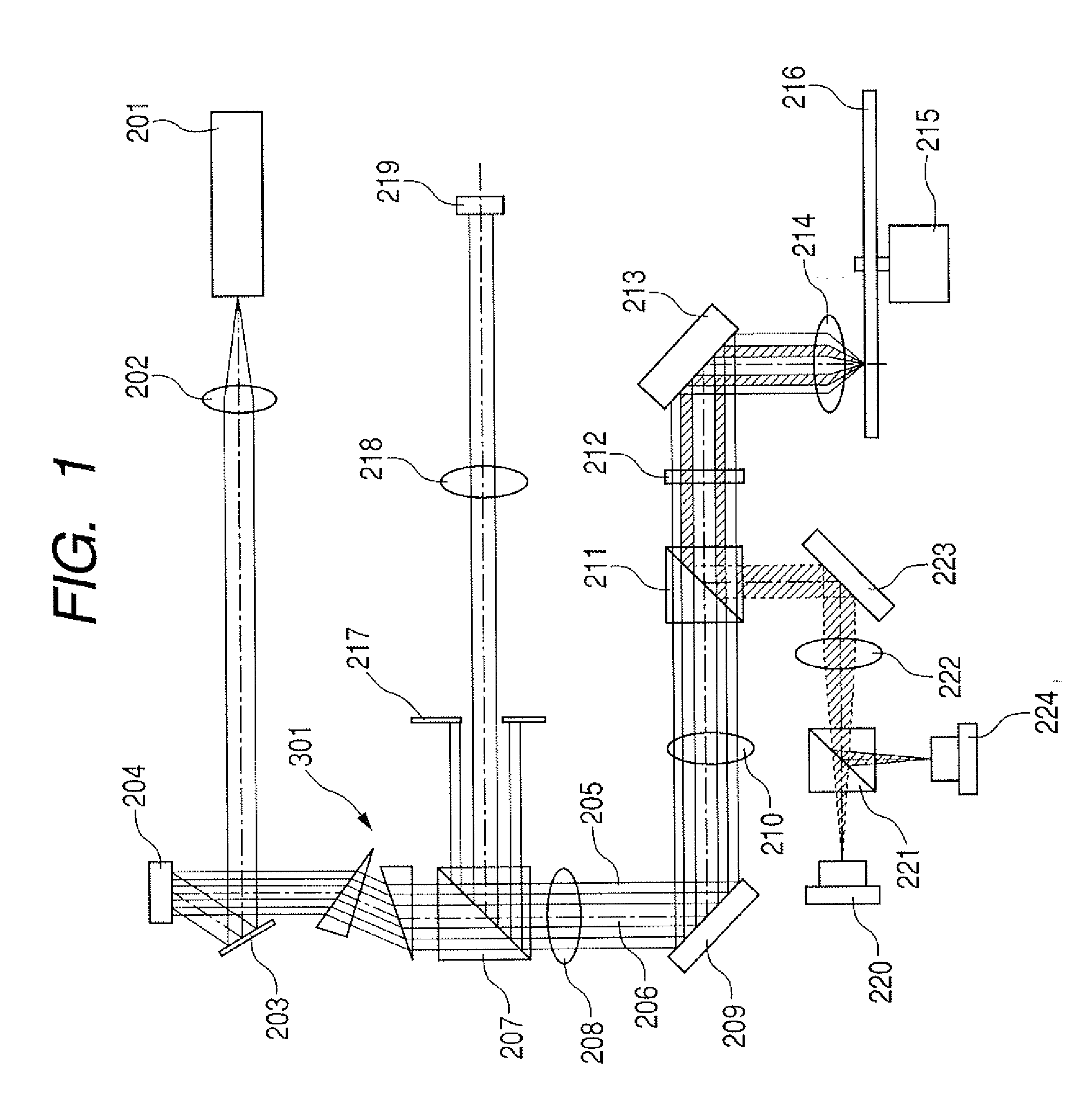
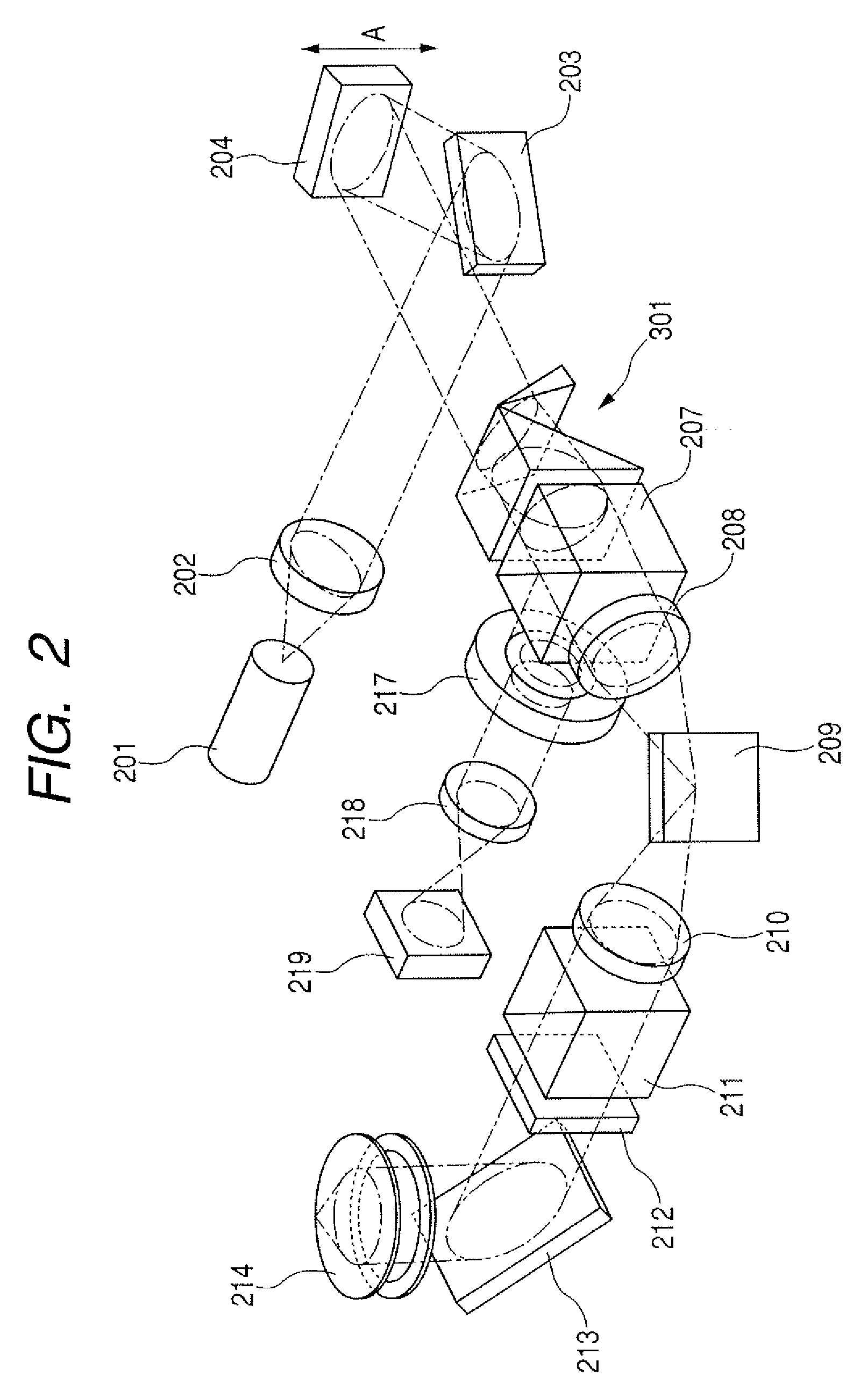
[0046]FIGS. 1 and 2 show a holographic optical pickup apparatus according to Embodiment 1 of the present invention. FIG. 1 is a developed view showing an optical system of the holographic optical pickup apparatus. FIG. 2 is a perspective view showing the optical system shown in FIG. 1, which is actually disposed in the optical pickup apparatus.

[0047] The fundamental structure shown in FIGS. 1 and 2 is identical to that of the optical system according to the conventional example as shown in FIG. 9. In FIGS. 1 and 2, the elements which are the same as those shown in FIG. 9 are identified by like numerals or symbols, and therefore detailed description thereof is omitted here. Incidentally, a hologram medium 216 having a disk shape as described later and the optical parts for performing the optical servo technique using the red laser described with reference to the conventional example are omitted in FIG. 2. In the developed view of FIG. 1, attention is focused on a short-axis of emitt...

embodiment 2

[0053]FIG. 4 is a view showing Embodiment 2 of the present invention. FIG. 4 is a developed view showing an optical system of a holographic optical pickup apparatus according to this embodiment. The fundamental structure is identical to that shown in FIGS. 1 and 2. In FIG. 4, the elements which are the same as those shown in FIGS. 1 and 2 are identified by like numerals or symbols, and therefore detailed description thereof is omitted here.

[0054] In this embodiment, a beam shaping prism 301 is disposed between a PBS 207 located subsequent to the spatial light modulator (SLM) 204, for guiding information light 206 as reproduced light to a CMOS sensor 219, and a relay lens-1208.

[0055] Next, a feature of the present embodiment will be described. At the time of reproduction, each of the information light 206 and the reference light 205 which are reproduced from the disk-shaped hologram medium 216 becomes circular polarizing light (for example, left-hand circular polarizing light) with...

embodiment 3

[0060]FIG. 5 is a view showing Embodiment 3 of the present invention. FIG. 5 is a developed view showing an optical system of an optical pickup apparatus according to this embodiment. The fundamental structure is identical to that of the optical system in Embodiment 1. In FIG. 5, the elements which are the same as those shown in FIGS. 1 and 2 are identified by like numerals or symbols, and therefore detailed description thereof is omitted here.

[0061] In this embodiment, a beam shaping mirror 302 is used as the beams shaping means and disposed between an objective lens 214 and a QWP 212. Therefore, the light beam emitted from a red laser 220 for optical servo, which is normally a semiconductor laser, can also be shaped therewith, so that the quality of red laser light for servo can be improved. Thus, in this embodiment, the red laser 220 is desirably disposed such that a short-axis of light having an elliptical sectional shape emitted therefrom is extended by the beam shaping mirror...


PUM

PropertyMeasurementUnit
shapeaaaaaaaaaa
densityaaaaaaaaaa
thicknessaaaaaaaaaa

Abstract

Provided is a holographic optical pickup apparatus which can be reduced in thickness and production cost while having a beam shaping unit. To be specific, in a holographic optical pickup apparatus based on a holographic memory technique, a beam shaping prism for extending a short axis of light with elliptical cross section emitted from a light source is disposed between a spatial light modulator (SLM) and an objective lens. Thereby, a light beam incident on the spatial light modulator (SLM) has an elliptical cross section and is small in diameter, so that the spatial light modulator can be reduced in size and cost.

Description

BACKGROUND OF THE INVENTION [0001] 1. Field of the Invention [0002] The present invention relates to a holographic optical pickup apparatus for recording or reproducing information to or from a recording medium by a holographic optical memory system. [0003] 2. Description of the Related Art [0004] In recent years, for super-high density optical recording, volume holography, in particular, digital volume holography has been practically developed and attention has been focused thereon. The term “volume holography” refers to a system for three-dimensionally writing an interference pattern on a recording medium by utilizing a thickness direction thereof as well. [0005] The system is advantageous in that the diffraction efficiency can be improved by an increase in thickness and the recording capacity can be increased using multiple recording. Further, the term “digital volume holography” refers to a holographic recording system in which image information to be recorded is limited to a bi...

Claims


Application Information

Patent Timeline
Patent Type & Authority Applications(United States)
IPC IPC(8): G11B7/00
CPCG11B7/0065G11B7/1398
Inventor TORII, SHINNOSUKE
Owner CANON KK
Why Eureka
Try Eureka