
Three sided swab

a three-sided swab technology, applied in the field of swab for cleaning, can solve the problems of difficult cleaning operation, dirt, oil and other debris on the connector itself, and the outer shells or shells of the connector can become dirty and soiled, so as to prevent over-saturation

Active Publication Date: 2007-06-07
ILLINOIS TOOL WORKS INC
View PDF7 Cites 3 Cited by
  • Summary
  • Abstract
  • Description
  • Claims
  • Application Information

AI Technical Summary

Benefits of technology

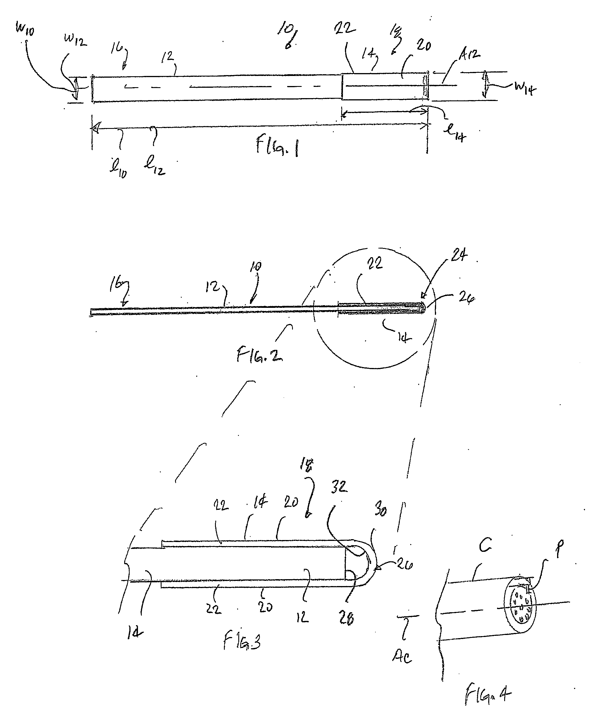
[0009] The swab is configured for use with multiple configurations and types of fiber optic connectors. The swab efficiently and effectively cleans both side and end faces of connectors. The inner annular cleaning surface is configured to clean connectors parts that extend generally normal to the longitudinal axis of the connector. Advantageously, the swab eliminates the need for maintaining an extensive inventory of different types of swabs for in-field fiber optic cable maintenance and repair. It is expected that the swab will be used in a lightly dampened state.
[0011] The cleaning head material is preferably a non-woven material. One suitable material is a synthetic chamois. The synthetic chamois can be a polyurethane or polyvinyl acetate material. The material can also be a micro denier material. The material should prevent over-saturating the fiber optic connection which can cause signal distortion.

Problems solved by technology

Moreover, when out “in the field”, the outer casings or shells of the connectors can become dirty and soiled from exposure to the environs.
As such, during maintenance and / or repair, the connectors themselves can become soiled with dirt, oils and other debris.
Since the connections are minute, most commonly there are strands that are “shrouded” by the alignment pins making cleaning a difficult operation.
One particular type of connector (an MT-type ribbon connector, which has alignment pins) can be very difficult to properly clean, especially the fibers that are along side of the alignment pins.
However, because of the different surfaces, pin configurations and the like, it has been found that for proper cleaning of these components, a one-size-fits-all cleaning implement is not the best solution.
And, it may not always be possible to have on hand all of the various sizes and configurations needed for a given use.

Method used


Image

  • Three sided swab
  • Three sided swab

Examples


Embodiment Construction

[0018] While the present invention is susceptible of embodiment in various forms, there is shown in the drawings and will hereinafter be described a presently preferred embodiment with the understanding that the present disclosure is to be considered an exemplification of the invention and is not intended to limit the invention to the specific embodiment illustrated.

[0019] It should be further understood that the title of this section of this specification, namely, “Detailed Description Of The Invention”, relates to a requirement of the United States Patent Office, and does not imply, nor should be inferred to limit the subject matter disclosed herein.

[0020] Referring to the figures and in particular to FIG. 1 there is shown a swab 10 in accordance with the principles of the present invention. The swab 10 includes a handle 12 and a cleaning head 14. The handle 12 has a grasping end 16 and a cleaning head end 18.

[0021] The cleaning head 14 is formed from a material that is applied...


PUM


Abstract

A cleaning swab is for wet or dry use. The swab includes a handle defining a longitudinal axis. The handle is elongated and has a cleaning head end having a tip, and a grasping end. A cleaning head is mounted to the handle. The cleaning head is formed from a strip of material having an inner surface and an outer surface. The material is affixed to the handle at the inner surface, and extends along the handle, over the tip and along an opposite side of the handle. The head defines a loop at the handle tip spaced from the tip. The strip of material extends along the handle to define major cleaning surfaces and the loop defines an inner annular cleaning surface.

Description

BACKGROUND OF THE INVENTION [0001] The present invention is directed to a swab for cleaning. More particularly, the present invention pertains to a swab having a different cleaning surfaces on a single cleaning head. [0002] Swabs are used in all manners of cleaning. For example, everyone will recognize common cotton tipped swabs that are used for person hygiene and care. Because of the compact and effective nature of these swabs, they have been adopted for use in numerous areas of technology and manufacture. One such area is the manufacture of advanced optical components for use in aerospace and navigation systems. [0003] Fiber optic components, such as fiber optic connectors, are also widely used in telecommunications. During manufacture and use of optical components it is not unusual for pieces of manufacturing debris, such as dust and fibers or other particulate debris to be left on surface of the components. It is also not unusual for light oils, such as fingerprint and other na...

Claims


Application Information

Patent Timeline
Patent Type & Authority Applications(United States)
IPC IPC(8): A47L13/10
CPCB08B1/00B08B2240/02G02B6/25G02B6/381G02B6/3866G02B6/3885B08B1/145
Inventor FOREST, EDWARD J.
Owner ILLINOIS TOOL WORKS INC
Learn More