
Device and method for the combustion of granular, solid fuel

a technology of solid fuel and combustion device, which is applied in the direction of combustion process, combustion type, lighting and heating apparatus, etc., can solve the problems of sinter formation inside the actual burner, mechanical breakdown, and serious disadvantage of the course, so as to facilitate the optimization of control of ignition and initiation

Inactive Publication Date: 2007-06-07
SWEDISH BIOBURNER SYST
View PDF8 Cites 17 Cited by
  • Summary
  • Abstract
  • Description
  • Claims
  • Application Information

AI Technical Summary

Benefits of technology

[0005] Thanks to the invention many advantages are gained. Firstly operational problems related to the movable ash feeder may practically be eliminated, since rather surprisingly the use of a temperature sensing means to disable operation of the movable ash feeder unless cooling to a certain temperature level has been achieved, has proven to drastically solve a numeral of experienced mechanical problems related to functioning thereof. Moreover the arrangement of a temperature sensor in close vicinity to the combustion chamber has proven to provide many other advantages such as facilitating optimised control regarding ignition and initiation of combustion.
[0009] a third sensor is connected to said control unit and positioned within said feeding and dosing unit to sense the pellet feeding temperature arranged to control safe shut-down to minimise risk of backfire.

Problems solved by technology

A great problem for traditional pellet burners is the sinter formation inside the actual burner.
The sintering obstructs the openings in the grate, why this normally must be taken out for cleaning at least once a week, occasionally a lot more often, which of course is a serious disadvantage.
However, also in connection with this new kind of burner device there are some problems.
Firstly it may happen that mall function occurs in connection with activation of the moveable ash feeder possibly leading to mechanical breakdown.
Moreover it has been discovered that it may be difficult to achieve optimised ignition timing and combustion timing during start up of a burner of this kind due to different flow patterns within the combustion chamber depending on varying parameters, e.g. amount of clogging of perforations, amount of a moisture, temperature of the pellets, etc.

Method used


Image

  • Device and method for the combustion of granular, solid fuel
  • Device and method for the combustion of granular, solid fuel
  • Device and method for the combustion of granular, solid fuel

Examples


Embodiment Construction

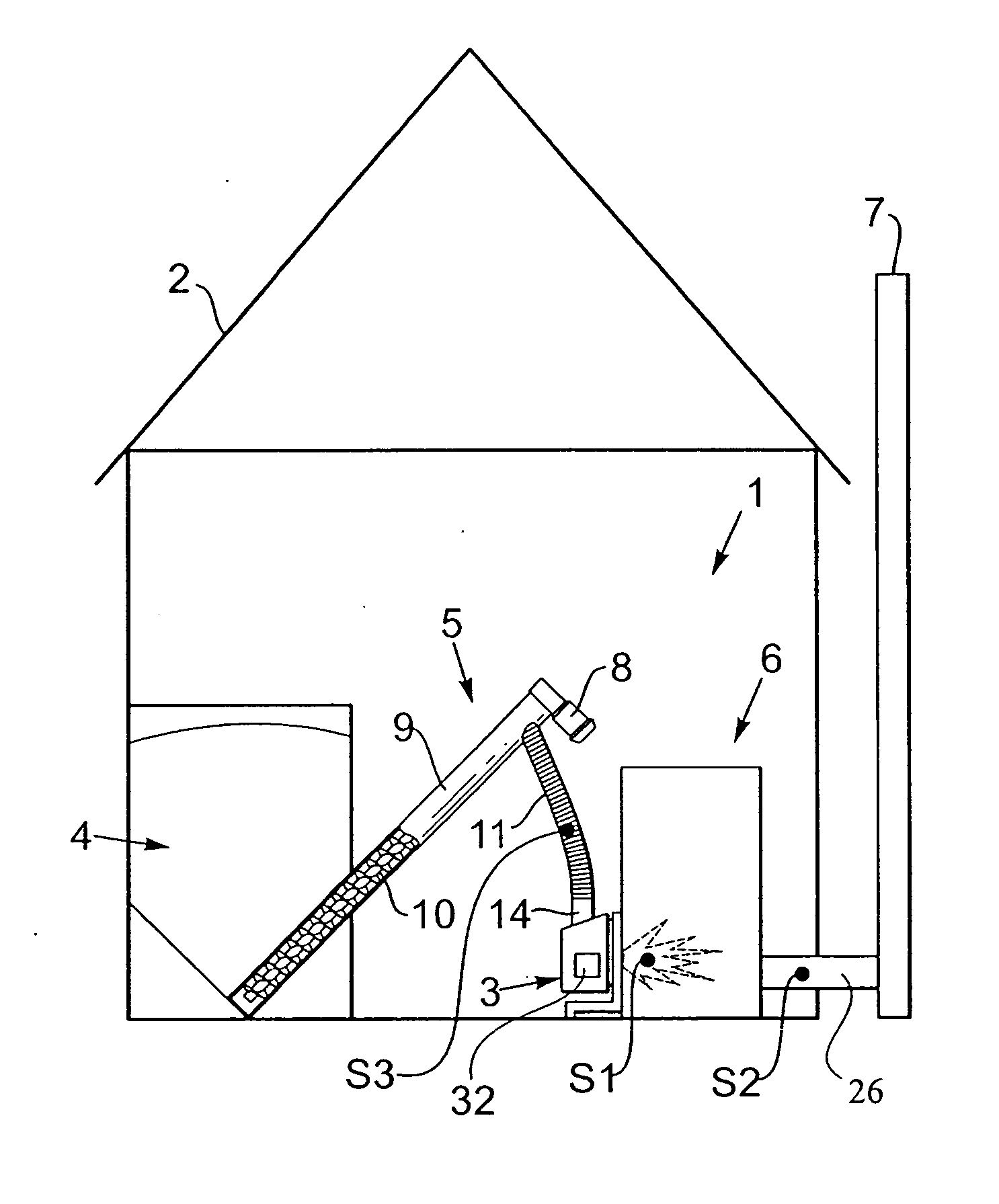
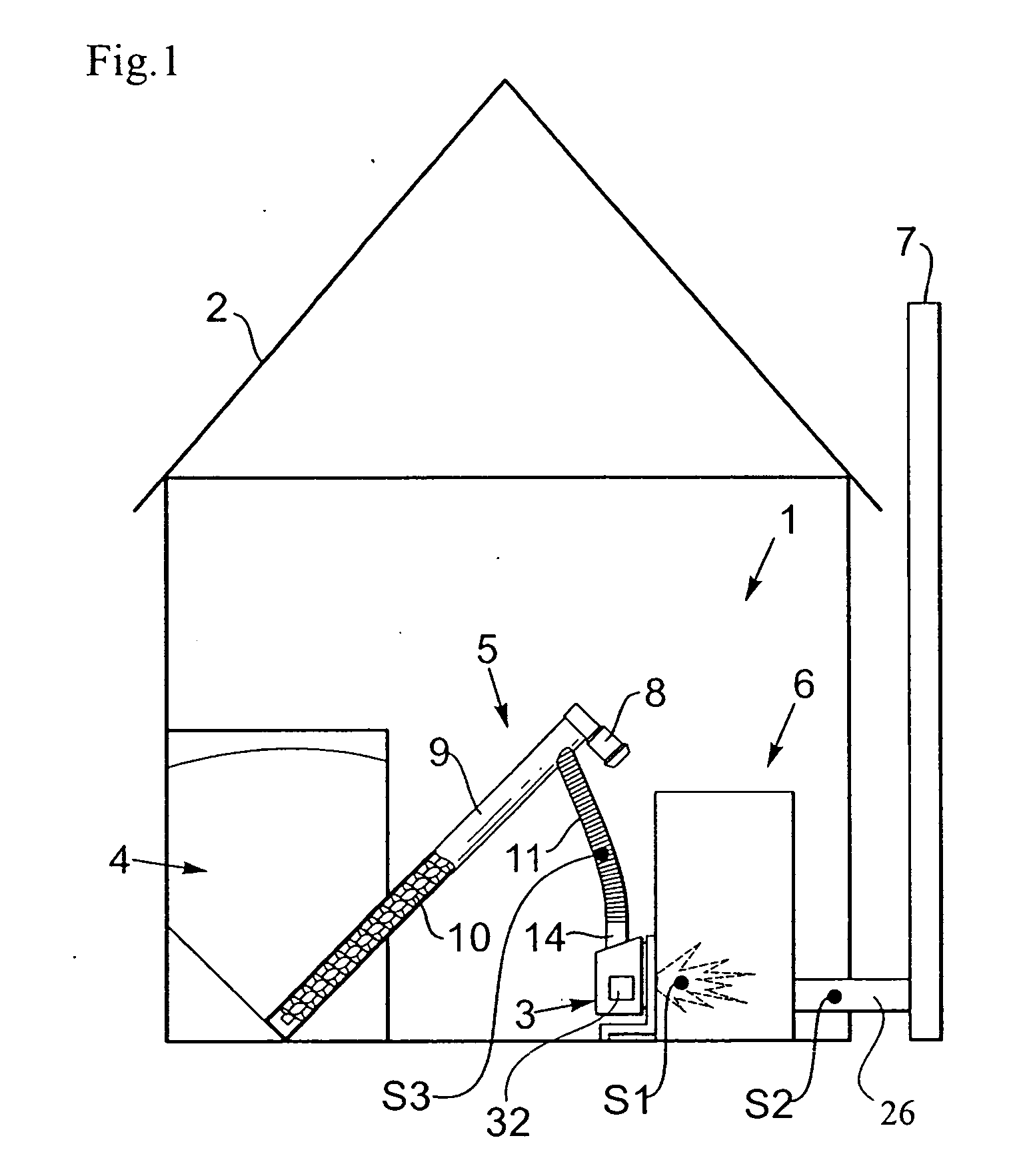
[0016] With reference to FIG. 1, it is shown a schematic view of parts of a device 3 for combustion of solid fuel in the form of granular materials, which is installed in a conventional central heating system 1 for heating of a house 2. Further there is shown a free standing fuel supply 4, at least one fuel conveyer 5, a conventional heating boiler 6 with a known heating system (not shown), and an outlet 26 to a chimney 7 for the fumes that are created.

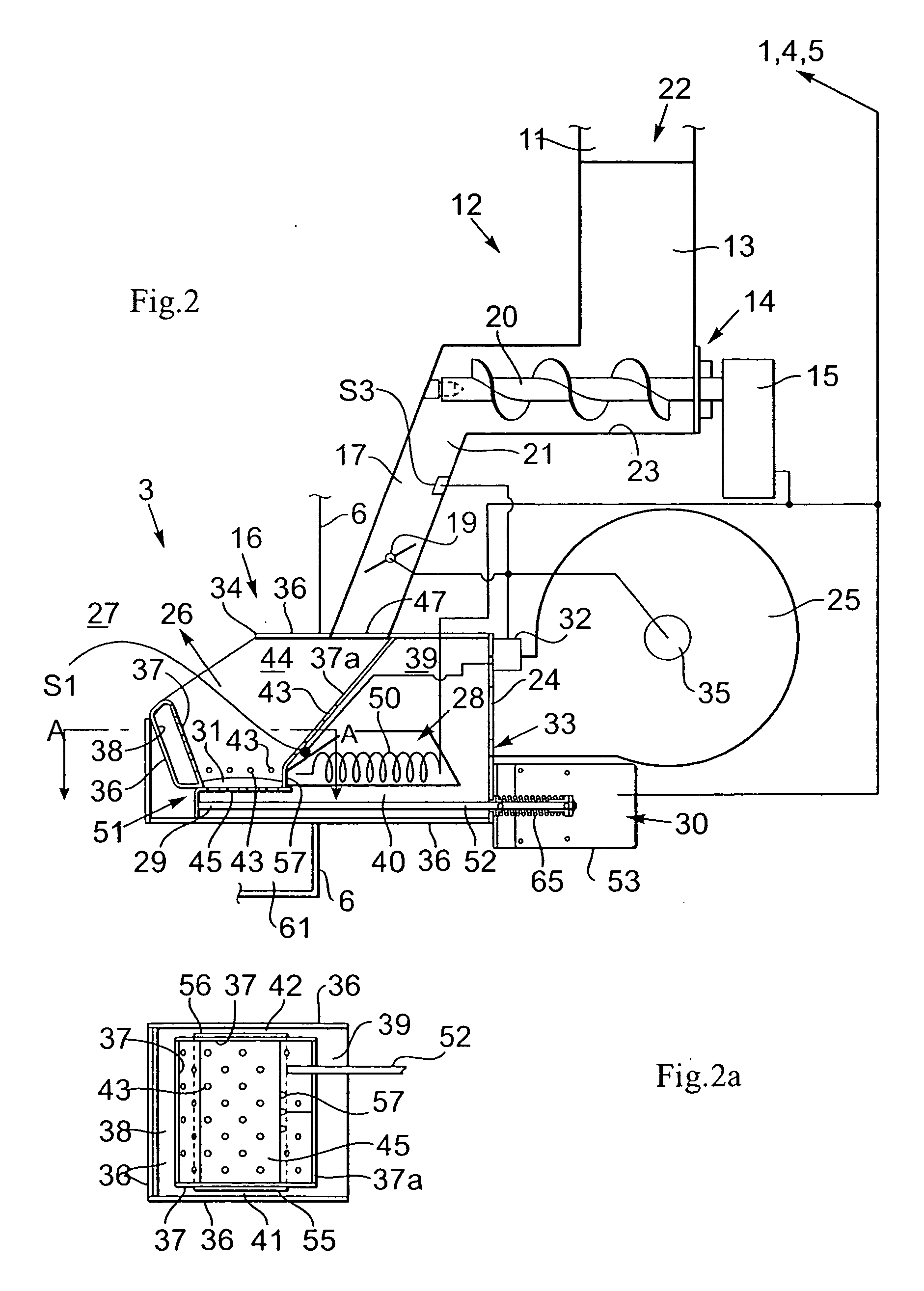
[0017] The fuel feeder comprises a motor 8 with a transmission box for operation of a feed screw 10, which is revolvably arranged in a feed tube 9 for automatic feeding of fuel from the fuel supply 4 through a down pipe 11, suitably in the form of a flexible hose, to a dosing device 12 in the combustion device 3. The fuel feeder 5 can also be provided with several feed screws 10, but also other types of known fuel feeders can of course be used. Further there is shown a control unit 32 for substantially all-automatic operation of the ...


PUM


Abstract

This invention relates to a device (3) for the combustion of granular, solid fuel, for example pellets and the like, comprising;a combustion chamber (16), an air inlet (24) for feeding air to the combustion chamber (16) via at least one air chamber (38,39,40) and at least one air-duct (41,42) for attaining an air flow through the combustion chamber (16), a feeding and dosing arrangement (10, 11, 12) for feeding of the fuel into the combustion chamber (16),an ignition device (28) for ignition of the fuel, a control unit (32) for operation of the combustion device (3) and parts co-operating therewith, an outlet (26) for hot combustion gases from the combustion chamber (16), a movably arranged ash feeder (29) with a drive unit (30), controlled by the control unit (32) for automatic feeding of ashes, unburned fuel, and slag products (31), out of the combustion chamber(16), wherein the ash feeder (29) comprises a movable front part (51) having a perforated bottom which constitutes the above mentioned inner bottom (45), movable between at least an operative position (58), shutting the lower end of the fire place (44), and an ash evacuating position (59), wherein a first temperature sensor (S2) positioned in vicinity of said combustion chamber (16), which first sensor is connected to said control unit (32) arranged to allow activation of said drive unit (30) only if the sensed temperature (T) is below a critical value (Tcr).

Description

TECHNICAL FIELD [0001] The present invention relates to a device for the combustion of granular, solid fuel, for example pellets and the like, comprising; a combustion chamber, an air inlet for feeding air to the combustion chamber via air chambers and air-ducts for attaining an air flow through the combustion chamber, a feeding and dosing arrangement for feeding of the fuel into the combustion chamber, an ignition device for ignition of the fuel, a control unit for operation of the combustion device and parts co-operating therewith, an outlet for hot combustion gases from the combustion chamber, a movably arranged ash feeder with a drive unit, controlled by the control unit for automatic feeding of ashes, unburned fuel, and slag products, out of the combustion chamber, wherein the ash feeder comprises a movable front part having a perforated bottom which constitutes the above mentioned inner bottom, movable between at least an operative position, shutting the lower end of the fire ...

Claims


Application Information

Patent Timeline
Patent Type & Authority Applications(United States)
IPC IPC(8): F23J1/00F23N5/02
CPCF23B50/12F23B60/02F23B99/00F23J1/06F23N5/24F23N2025/16F23N2031/28F23N2225/16F23N2231/28
Inventor INGVARSSON, ROBERT
Owner SWEDISH BIOBURNER SYST
Learn More