Large field of view modulating retro reflector (MRR) for free space optical communication

a technology of free space optical communication and large field of view, which is applied in the direction of fibre transmission, multi-station single light source, electrical apparatus, etc., can solve the problems of reducing the applicability of mobile communication systems, reducing the initial alignment of communication links or potentially maintaining connectivity in mobile communication environments, and hardware may not be sufficiently rugged for a mobile environmen

Inactive Publication Date: 2007-06-07
CUBIC CORPORATION
View PDF5 Cites 36 Cited by
  • Summary
  • Abstract
  • Description
  • Claims
  • Application Information

AI Technical Summary

Benefits of technology

[0006] Embodiments of a modulating retro-reflector (MRR) configured to provide a large field of view and a transponder using one or more MRRs is disclosed. The MRR can include a solid corner cube reflector (CCR) manufactured of a material having a high index of refraction at the desired operating wavelength. The high index materials can include Indium Phosphide (InP) or monocrystalline optical grade Silicon (Si), and can provide an index of refraction of greater than 1.5 or greater than 3 and approximately 3.4 at an operating wavelength of approximately 1550 nm. Each CCR can include one or more elements configured to modulate an optical signal incident on the CCR. The modulating element can be positioned on the front surface of the CCR or can be positioned on one or more of the back, or reflecting, surfaces of the CCR.

Problems solved by technology

Some aspects of an optical communication system that may be advantageous in an application may present a problem in another.
For example, the highly directional narrow laser beam associated with a free space laser transmitter can present problems of initially aligning the communication link or potentially maintaining connectivity in mobile communication environments.
An optical communication system typically employs an optical transmitter and a receiver that could present portability issues in a mobile communication system.
This would reduce the applicability in mobile communication systems because it would be difficult to transported by an individual.
Additionally, such hardware may not be sufficiently rugged for a mobile environment.
The weight of optical hardware and mechanical supports may also limit the appeal of optical communications for mobile communications.

Method used


Image

  • Large field of view modulating retro reflector (MRR) for free space optical communication
  • Large field of view modulating retro reflector (MRR) for free space optical communication
  • Large field of view modulating retro reflector (MRR) for free space optical communication

Examples


Embodiment Construction

[0019] A Modulating Retro-Reflector for use in optical communication systems can be configured to have a wide Field Of View (FOV). A large FOV modulating retro-reflector can be used to provide substantially angle independence reception of directional laser beams. A transponder / tag utilizes fewer wide FOV modulating retro-reflectors to support a predetermined coverage. Each of the modulating retro-reflectors can be configured to include a solid Comer Cube Reflector (CCR) manufactured of a high index of refraction material. Such high index of refraction material refers to an index of refraction greater than about 1.5 at the operating wavelength. However, the high index of refraction may be greater than about 1.75, 2.0, 2.25, 2.5, 2.75, 3.0, 3.25, 3.5, or some other index of refraction value.

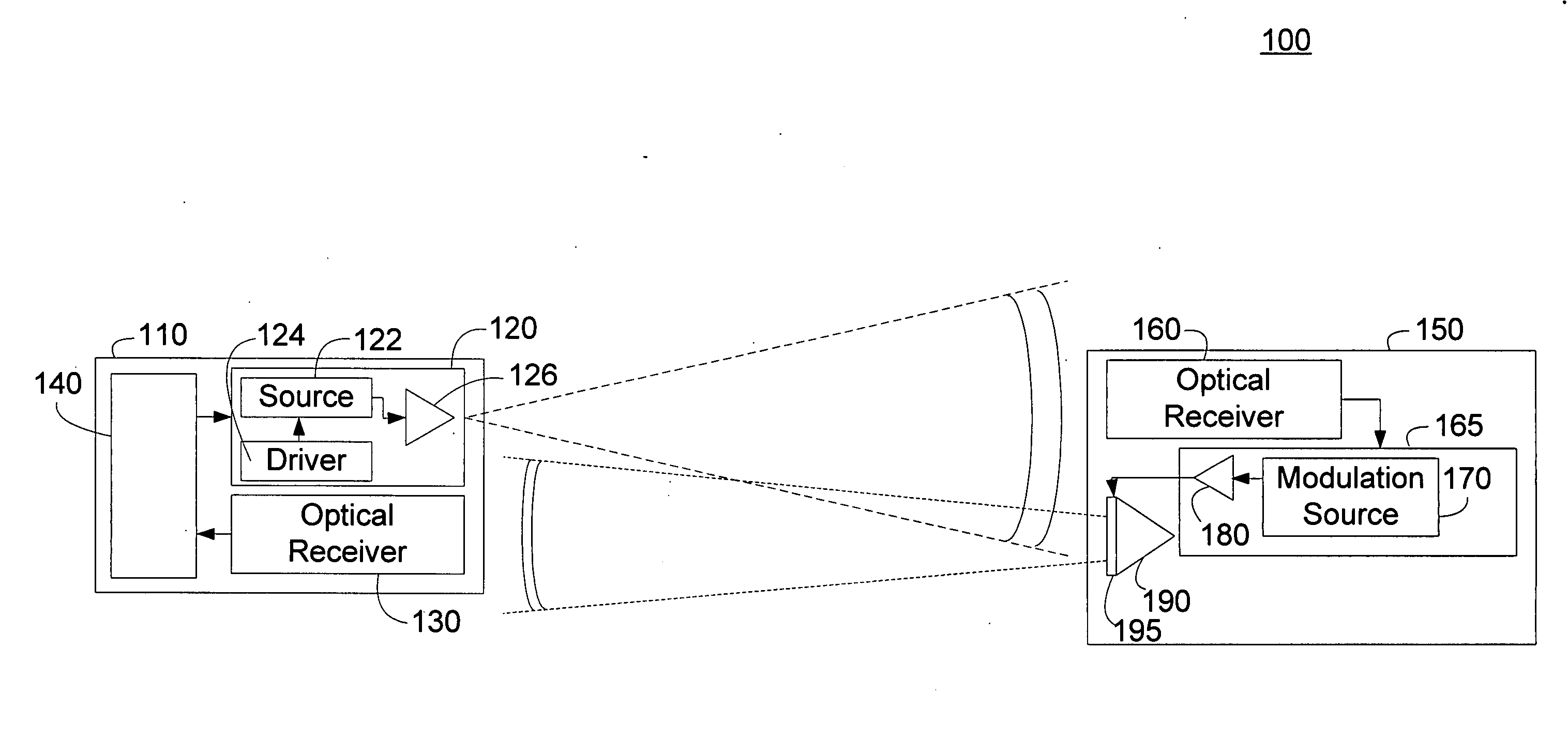
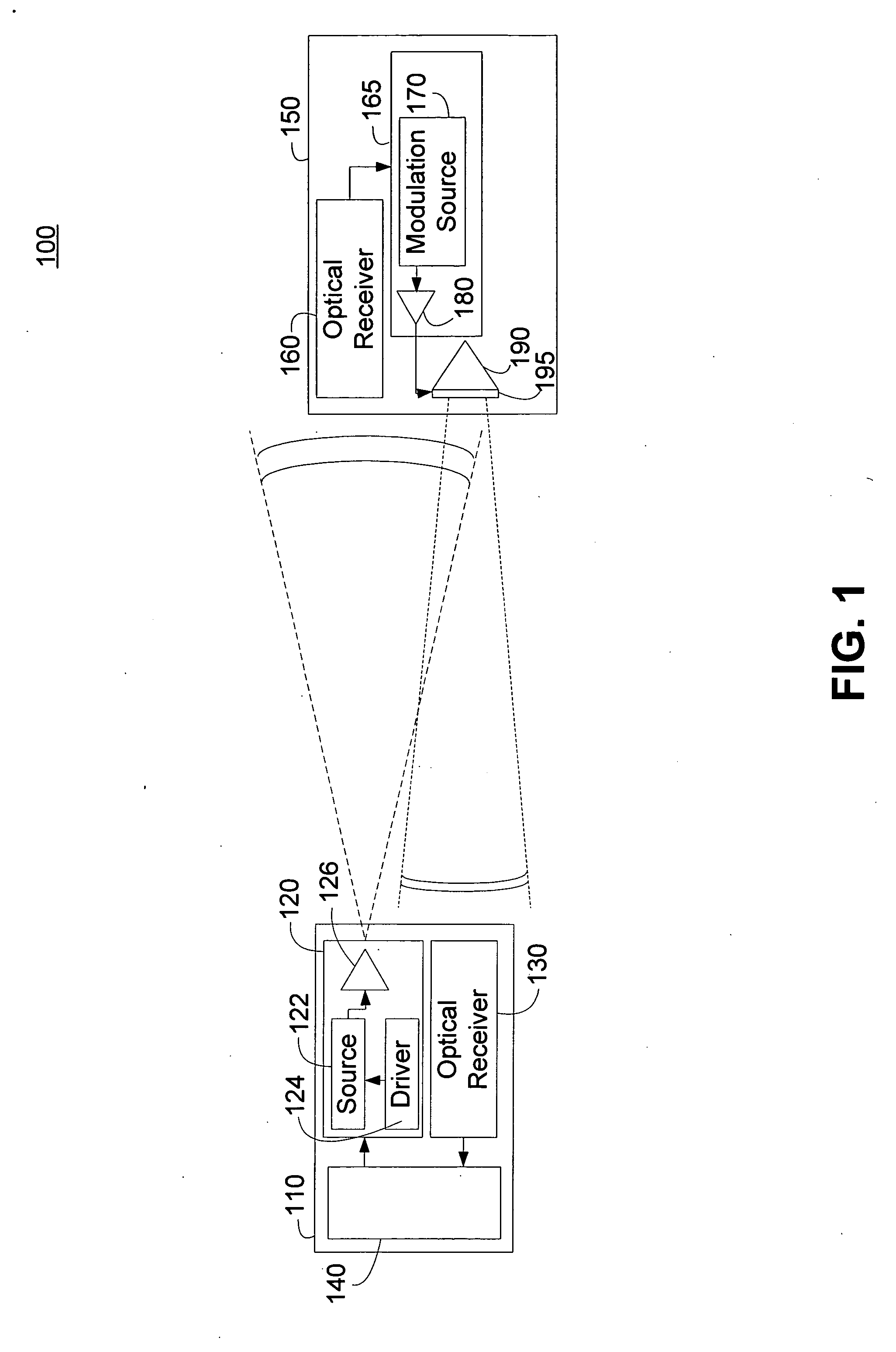
[0020]FIG. 1 is a simplified functional block diagram of an embodiment of a free space optical system 100 that can utilize the disclosed optical source and method of generating a modulated carrier...


PUM


Abstract

A modulating retro-reflector (MRR) can be configured to provide a large field of view. The MRR can include a solid corner cube reflector (CCR) manufactured of a material having a high index of refraction at the desired operating wavelength. CCRs made from high index materials such as InP or Si, have an index of refraction of approximately 3.48 at an operating wavelength of approximately 1550 nm and can provide a conical Field of View (FOV) of greater than ±60 degrees compared to less than ±30 degrees for CCRs made from BK-7. Each CCR can include one or more elements configured to modulate an optical signal incident on the CCR. A retro-modulating transponder can use fewer large FOV MRRs to support communication over a predetermined incident optical span compared to narrower FOV MRRs resulting in lower cost, smaller size, weight and power requirements.

Description

BACKGROUND OF RELATED ART [0001] Optical communication systems are advantageously implemented to support communications in a variety of operational situations. An optical communication system can offer many features and advantages not available from other systems. An optical communication system can typically provide an information bandwidth not available from other communication systems. A free space optical communication system can provide a line of sight link without the need to establish any wired infrastructure between the access points of the link. A free space optical communication link typically utilizes highly directional narrow divergence laser beams, thereby minimizing the opportunity for detection or interception of the signals and receivers that may have relatively narrow field of view (FOV), limiting the amount of noise and interference received from undesired or unintentional optical sources. [0002] Some aspects of an optical communication system that may be advantage...

Claims


Application Information

Patent Timeline
Patent Type & Authority Applications(United States)
IPC IPC(8): H04B10/00
CPCH04B10/2587
Inventor VARSHNEYA, DEEPAKTAYLOR, CHRIS
Owner CUBIC CORPORATION
Why Eureka
Try Eureka