Substrate heat treatment apparatus

Active Publication Date: 2007-06-07
DAINIPPON SCREEN MTG CO LTD
View PDF4 Cites 34 Cited by
  • Summary
  • Abstract
  • Description
  • Claims
  • Application Information

AI Technical Summary

Benefits of technology

[0016] According to this invention, the flexion elements can form closed spaces communicating with the perforations even when the transfer pins move up and down inside the perforations. Consequently, gastightness of the space formed between the substrate and heat-treating plate and closed by the closing device is never impaired through the perforations. The s

Problems solved by technology

However, with enlarged substrate sizes, increased curvatures of substrates take place in the semiconductor manufacturing process.
It is difficult to satisfy the requirements for temperature uniformity in a proximity heating mode that heats each substrate only by placing the substrate as separated by a minute space from a heat-treating plate.
Since the transfer pins

Method used


Image

  • Substrate heat treatment apparatus
  • Substrate heat treatment apparatus
  • Substrate heat treatment apparatus

Examples


embodiment 1

[0031] Embodiment 1 of this invention will be described hereinafter with reference to the drawings.

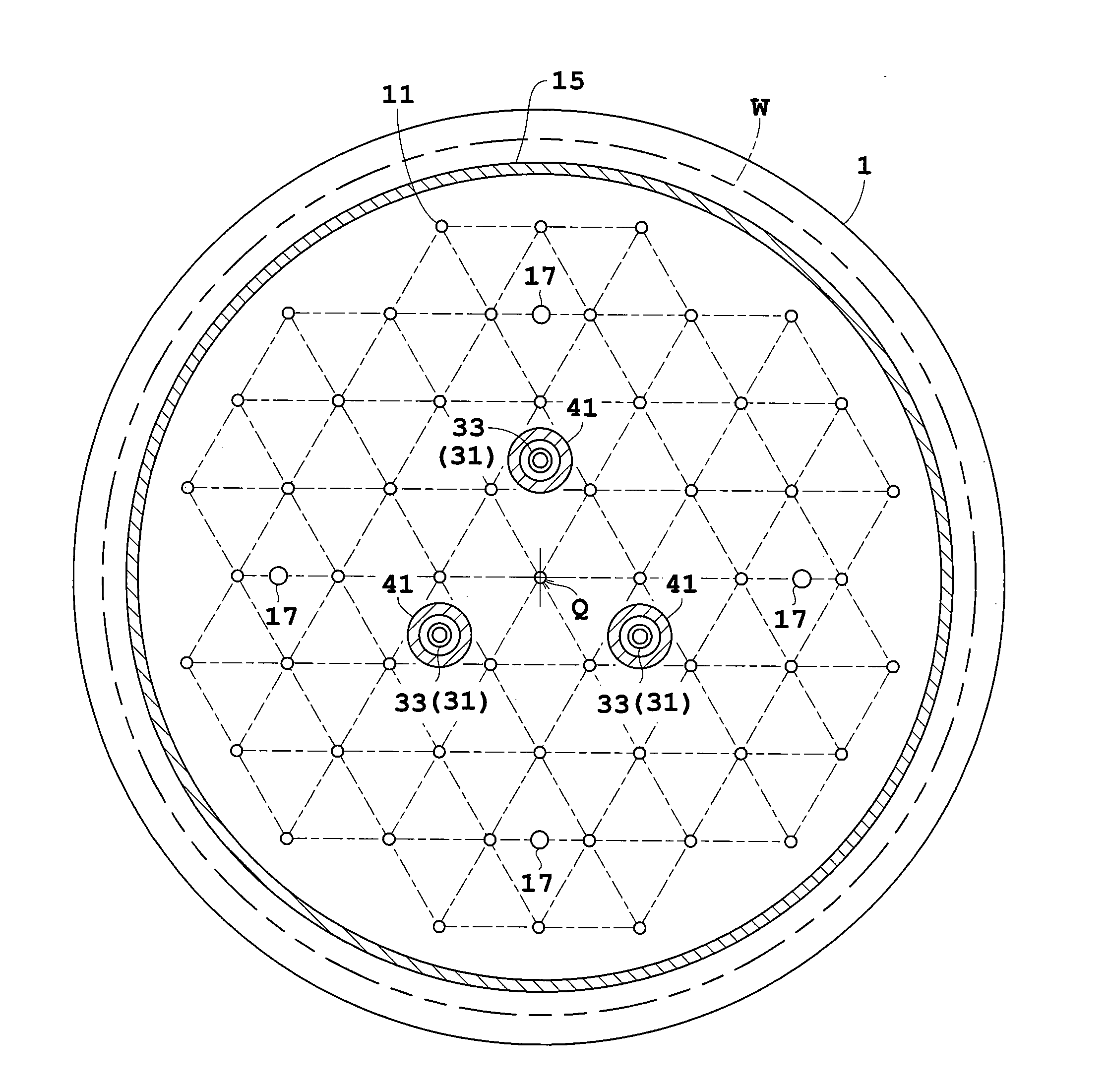
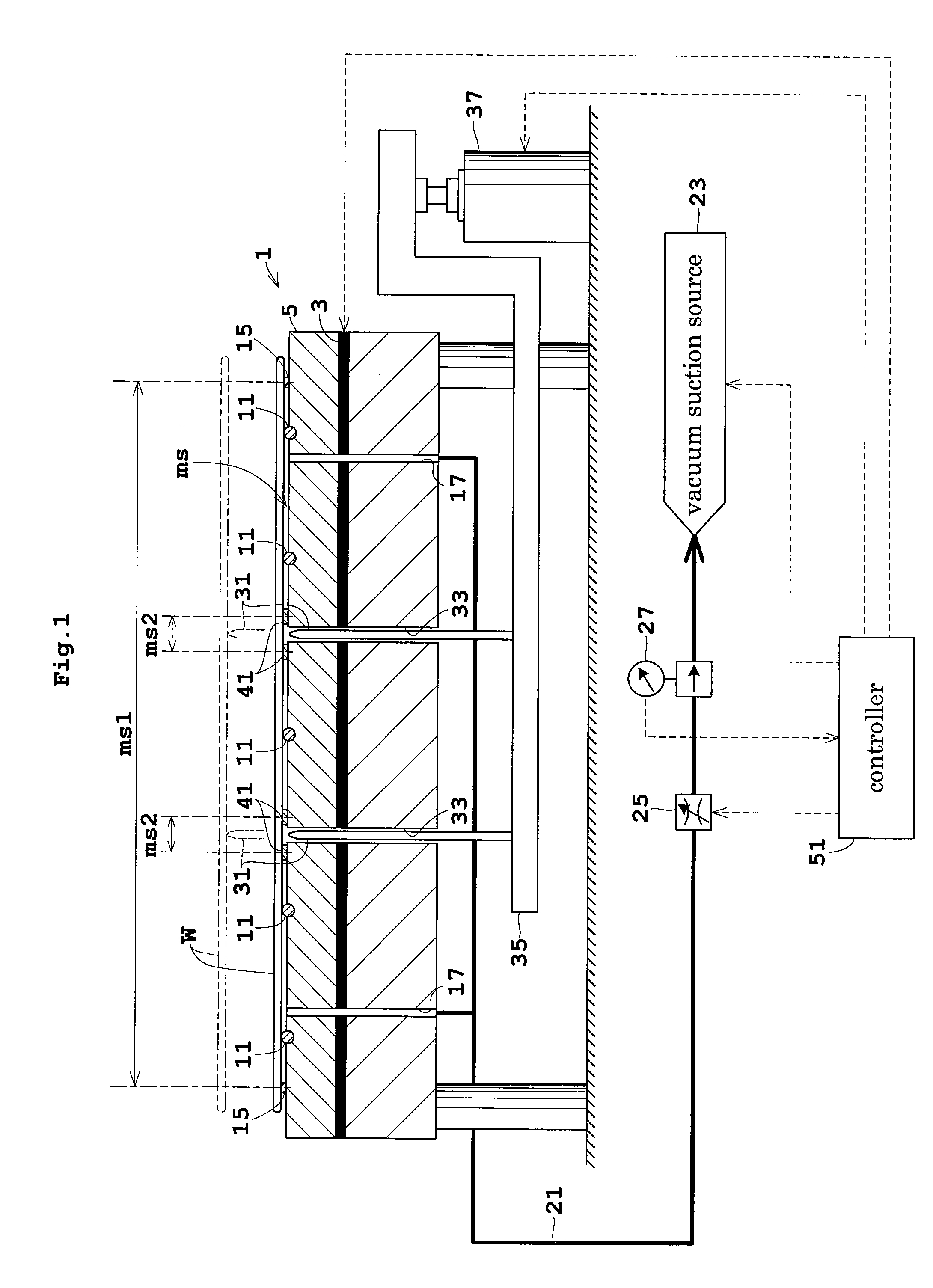
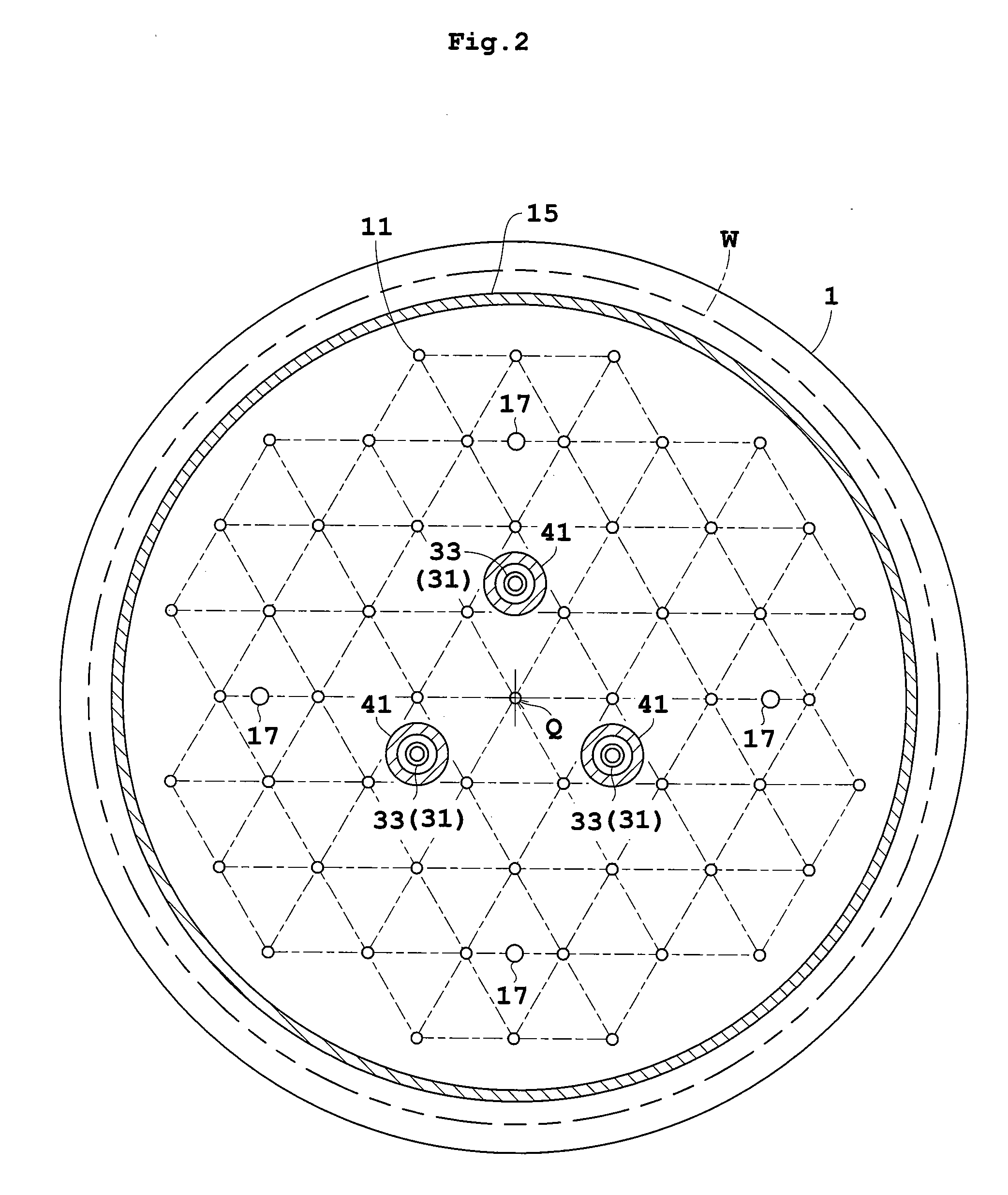
[0032]FIG. 1 is a view in vertical section showing an outline of a substrate heat treatment apparatus in Embodiment 1. FIG. 2 is a plan view of a heat-treating plate.

[0033] A heat-treating plate 1 for supporting a substrate or wafer W under treatment on an upper surface thereof has a heating element 3 such as a mica heater mounted therein. A heat transfer portion 5 between the heating element 3 and the upper surface of heat-treating plate 1 has a plurality of heat pipes, not shown, embedded therein. Cooling grooves, not shown, are formed between the heat pipes for circulating a cooling fluid.

[0034] The heat-treating plate 1 has a plurality of support elements 11 arranged on the upper surface thereof for contacting and supporting the lower surface of the wafer W. As shown in FIG. 2, the support elements 11 are arranged regularly on the upper surface of the heat-treating plate 1. In t...

embodiment 2

[0060] Embodiment 2 of this invention will be described hereinafter with reference to FIG. 7. Like reference numerals are used to identify like parts which are the same as in Embodiment 1 and will not particularly be described. FIG. 7 is a view in vertical section showing an outline of a substrate heat treatment apparatus in Embodiment 2.

[0061] Embodiment 2 is directed to a substrate heat treatment apparatus having slide contact elements 43 in place of the second sealers 41 in Embodiment 1. The slide contact elements 43 are provided for the openings of the perforations 33 in the lower surface of heat-treating plate 1. The slide contact elements 43 are ring-shaped, and have an inside diameter corresponding to the outside diameter of transfer pins 31. The transfer pins 31 slidably extend through the center openings of the slide contact elements 43, respectively. Thus, the slide contact elements 43 close the perforations 33 (i.e. apply shaft seals) while being in sliding contact with ...

embodiment 3

[0065] Embodiment 3 of this invention will be described hereinafter with reference to FIG. 8. Like reference numerals are used to identify like parts which are the same as in Embodiment 1 and will not particularly be described. FIG. 8 is a view in vertical section showing an outline of a substrate heat treatment apparatus in Embodiment 3.

[0066] Embodiment 3 is directed to a substrate heat treatment apparatus having flexion elements 45 in place of the second sealers 41 in Embodiment 1. The flexion elements 45 are in the form of bellows-like tubes vertically expandable and contractible. The flexion elements 45 have upper ends thereof secured to positions surrounding the openings of the perforations 33 in the lower surface of heat-treating plate 1. The lower ends of the flexion elements 45 are secured to the support base 35 to surround the transfer pins 31. The flexion elements 45 define closed spaces Sc therein communicating with the perforations 33, respectively.

[0067] When a wafer...


PUM

PropertyMeasurementUnit
Widthaaaaaaaaaa
Heightaaaaaaaaaa
Elasticityaaaaaaaaaa

Abstract

A heat-treating plate has, arranged on the upper surface thereof, support elements for supporting a substrate, and a first sealer for closing lateral areas of a first space formed between the heat-treating plate and the substrate supported. Further, second sealers ring-shaped in plan view are arranged around openings of perforations accommodating transfer pins. The second sealers close lateral areas of second spaces opposed to the perforations. Gastightness of the first space excluding the second spaces is never impaired through the perforations. By exhausting gas from the first space through exhaust bores, the substrate is effectively sucked for heat treatment.

Description

BACKGROUND OF THE INVENTION [0001] (1) Field of the Invention [0002] This invention relates to a substrate heat treatment apparatus for heat-treating substrates such as semiconductor wafers, glass substrates for liquid crystal displays, glass substrates for photomasks and substrates for optical disks (hereinafter simply called “substrates”). More particularly, the invention relates to a technique for heat-treating a substrate as sucked in a position slightly spaced from a heat-treating plate. [0003] (2) Description of the Related Art [0004] With an increasingly fine line width of patterns formed on substrates today, the requirements for line width uniformity have become stringent, which has led to a strong demand for temperature uniformity in baking treatment in photolithography, especially in baking treatment after exposure (PEB: Post Exposure Bake). However, with enlarged substrate sizes, increased curvatures of substrates take place in the semiconductor manufacturing process. It ...

Claims


Application Information

Patent Timeline
IPC IPC(8): H01L21/4763H01L21/00
CPCH01L21/67103H01L21/6838H01L21/68742H01L21/6875
Inventor GOTO, SHIGEHIROMATSUCHIKA, KEIJI
Owner DAINIPPON SCREEN MTG CO LTD
Why Eureka
Try Eureka