Flexible light sources and detectors and applications thereof

a light source and flexible technology, applied in the field of optoelectronic devices, can solve the problems of limiting the curvature of the sensor device, affecting the optical contact between the sensor components and the patient's skin, and affecting the patient's health,

Inactive Publication Date: 2007-06-07
QINETIQ LTD
View PDF17 Cites 79 Cited by
  • Summary
  • Abstract
  • Description
  • Claims
  • Application Information

AI Technical Summary

Benefits of technology

[0026] Advantageously, a closer and more stable fit can be provided to the patient's body.

Problems solved by technology

However even these are far too large for premature and small babies, who need intensive monitoring.
However, referring to FIG. 1(a), a known problem with such sensors is that known LEDs 73 are made inside rigid glass or plastic cases which significantly limits the curvature of the sensor device achievable when applying the oximeter to the patient 61.
In some cases it is also difficult to achieve good optical contact between the sensor components and the patient's skin owing to the undesirably large size and inflexibility of the sensor components.
Since such sensors cannot, for example, closely follow the tight skin curvature of a tiny baby, the sensors are prone to becoming detached or moving with respect to the patient during use and may thereby give rise to false alarms.
A further well-known problem associated with existing oximeters, and similar sensors, is the so-called “penumbra effect”.
Because known LEDs are discrete rigid devices and effectively provide point sources of light, they cannot typically be sufficiently closely located adjacent one another to ensure that the respective paths to the detector are consistently sufficiently close when the device is actually applied to the patient.
Consequently this adds to the difficulties in siting the sensors on a patient and the potential uncertainty of the readings obtained.
The rigid nature of the electronic components of existing sensors means that the sensor's carrying strip 71 does not follow well the patients' contours.
However, the use of self-adhesive strips has the undesirable side-effect of causing skin irritation in some cases—particularly in young babies—and such strips must therefore be re-sited frequently (for example every 3-4 hours).
Because of this, such sensors are often applied over the foot, even when this site is not otherwise ideal for monitoring the patient, whether medically or for the patent's comfort.
However the lack, in known sensors, of a snug fit around the patient—owing at least in part to the rigid nature of some component parts—means that use of such fastening means alone in known sensors in place of self-adhesion would lead to an arrangement in which the electronic components would be prone to rocking or slipping around the patient.
This in turn would give rise to inaccurate readings and ultimately to false alarms were the oximeter to loosen or detach entirely from the patient.
Consequently, some parts of the body may be exposed which do not require specific treatment and, since light from the source is dissipated widely, the available light is also not efficiently directed to the area to be treated.
Unfortunately, and particularly in the case where the patient has taken the sensitsing agent in tablet form rather than applying the cream to the affected area to be treated, there is an associated danger of eye damage arising from inadvertent exposure of the eyes to the UVA lamp during treatment.
The tumour sites are then irradiated with light at a predetermined wavelength (typically in the red spectrum) which is absorbed by the dyes, resulting in damage to tumour cells where the dye has accumulated.
However this is designed to detect in the UV spectrum, and although it describes dopants to extend the sensitivity into the visible, these would be unsuitable for detection of red or near infra-red (NIR).

Method used


Image

  • Flexible light sources and detectors and applications thereof
  • Flexible light sources and detectors and applications thereof
  • Flexible light sources and detectors and applications thereof

Examples


Embodiment Construction

[0077] The present inventors have identified that the use of flexible LEDs (for example organic LEDs or polymer based light sources, formed upon flexible substrates) as medical light sources offers many advantages over known light sources for diagnostic and therapeutic purposes.

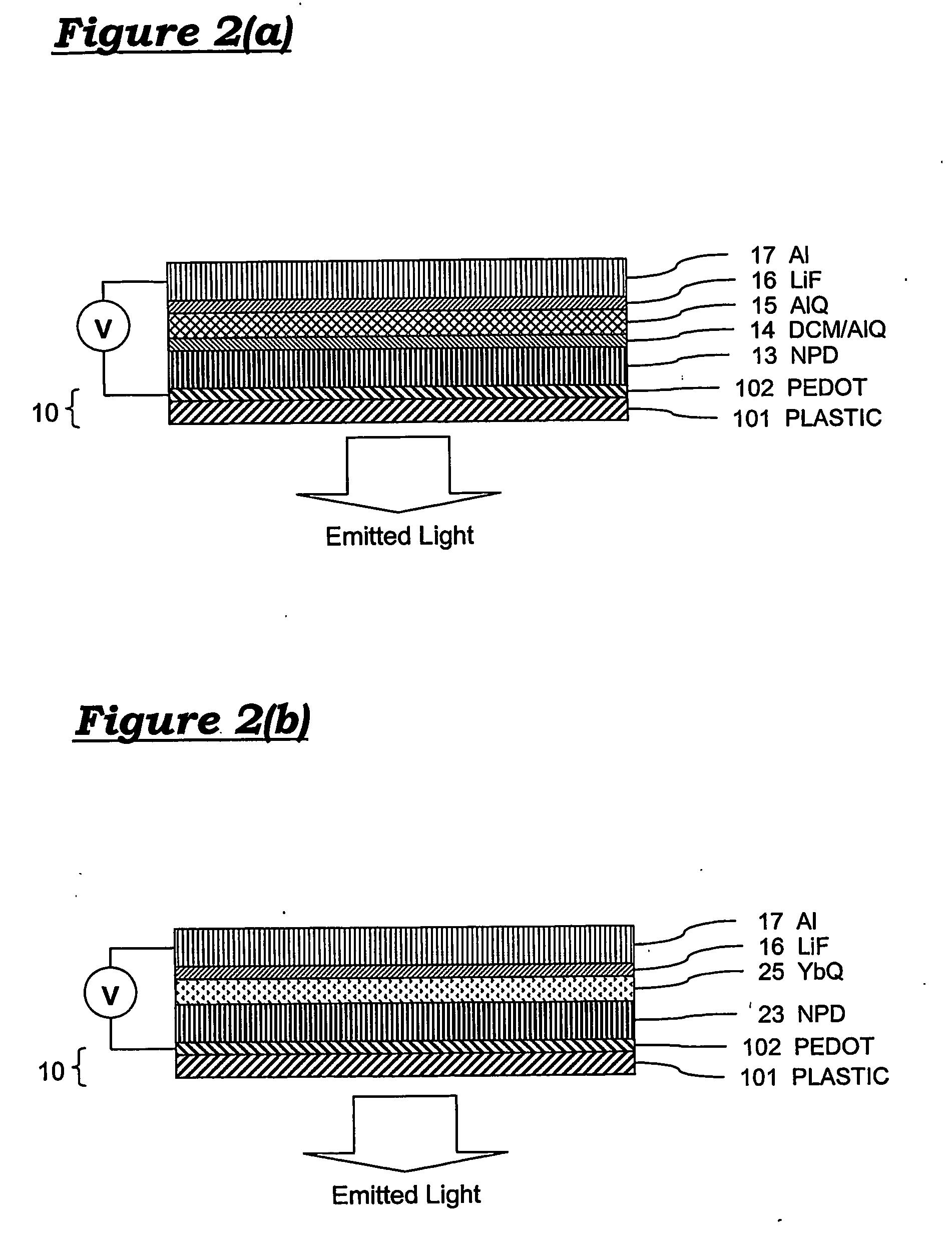
[0078] Referring to FIG. 2(a), a first embodiment of a flexible organic light emitting diode is formed upon a plastic substrate 10, which may be approximately 50 mm long and 13 mm wide. ORGACON™ flexible substrate (AGFA) may be used. ORGACON is a commercially available PET (Poly Ethylene Terephthalate) film 101 coated with a conductive polymer (PEDOT / PSS—Polyethylene-Dioxythiophene in Polystyrenesulphonic acid) 102. Several varieties of ORGACON are available, of which a preferred variety provides a substrate which is 125 microns thick and has sheet resistance of 350 ohms / square. The OLED is formed upon the substrate by forming successive layers as follows.

[0079] Further layers are then evaporated onto the f...


PUM


Abstract

Flexible and conformal medical light sources and related diagnostic devices directed to monitoring blood characteristics (e.g. levels of CO, oxygen, or bilirubin) and photo-therapeutic devices for treatment of ailments such as psoriasis and some forms of cancer. The flexible light source preferably comprises one or more organic light emitting diodes on a flexible substrate. Light sources may also be used for purposes of treatment. The substrate can also form a integral strap for attachment of the device over or around the patient's body. Optionally, the device comprises a photo-detector arranged to detect and monitor emissions from the sources. Flexible and conformal medical light detectors and devices are also provided.

Description

FIELD OF THE INVENTION [0001] The present invention relates to optoelectronic devices in general and in particular to flexible light sources (for example organic light emitting diodes) and detectors, and applications thereof. Applications include, but are not limited to, use in medical applications including therapeutic light sources and patient monitoring equipment. BACKGROUND TO THE INVENTION [0002] The use of light sources for medical purposes is well known, and may be broadly categorised into use for monitoring purposes and use for therapeutic purposes. [0003] For monitoring purposes it is well-known to use light sources in monitoring devices which take advantage of the absorption spectrum of various blood constituents to facilitate non-intrusive detection of human and animal patient blood characteristics. [0004] One such device is the pulse oximeter, and such devices have been in common use in hospital operating theatres since the 1970's. In more recent years such devices have ...

Claims


Application Information

Patent Timeline
Patent Type & Authority Applications(United States)
IPC IPC(8): A61B5/00A61B17/00A61N5/06H01L51/00
CPCA61B5/14546A61B5/14552A61B2017/00057A61N5/062A61N2005/0645A61N2005/0651A61N2005/0653H01L51/5016H01L51/5262H01L51/5265H10K50/11H10K2101/10H10K50/852H10K50/85
Inventor ROCHESTER, KATIESAGE, IAN CHARLESKAUSHAL, TEJ PAUL
Owner QINETIQ LTD
Why Eureka
Try Eureka