
Lightweight management and high availability controller

Inactive Publication Date: 2007-06-07
HEWLETT-PACKARD ENTERPRISE DEV LP
View PDF6 Cites 2 Cited by
  • Summary
  • Abstract
  • Description
  • Claims
  • Application Information

AI Technical Summary

Benefits of technology

[0019] It is another object of the present invention to reduce the susceptibility to corruption of network storage appliance firmware and configuration.
[0023] The present invention provides, in a fourth aspect, a method of reducing the possibility for corruption of firmware and configuration for a network storage appliance. The method comprises providing a network storage appliance of the second aspect, loading firmware and configuration on startup from the nonvolatile storage to the main computing unit, and electronically disconnecting the nonvolatile storage from the main computing unit after loading.
[0025] The present invention is particularly suitable for low-cost, highly flexible designs based on standard hardware. For example, the main computing unit could be an unaltered, standard PC motherboard with no support for high availability. The present invention introduces high availability features typically found in high-end equipment with expensive, proprietary hardware to this low-cost main computing unit.

Problems solved by technology

As one skilled in the art will know, and except in some more complex scenarios, the two appliances should not provide the same service simultaneously, as that could lead to data corruption.
While redundant network storage appliances do provide high availability in most cases, if communication between the redundant appliances goes down, but the appliances themselves are still operational, there is no way for either of them to know that the other is still up.
This common clustering problem is known as “split brain.” This condition can also result in the more complex scenarios noted above where simultaneous servicing is possible, since even in those situations, the appliances must still communicate and synchronize.
Another problem with network storage appliances is the susceptibility to corruption of the firmware and configuration from viruses, malware and other means.

Method used


Image

  • Lightweight management and high availability controller
  • Lightweight management and high availability controller

Examples


Embodiment Construction

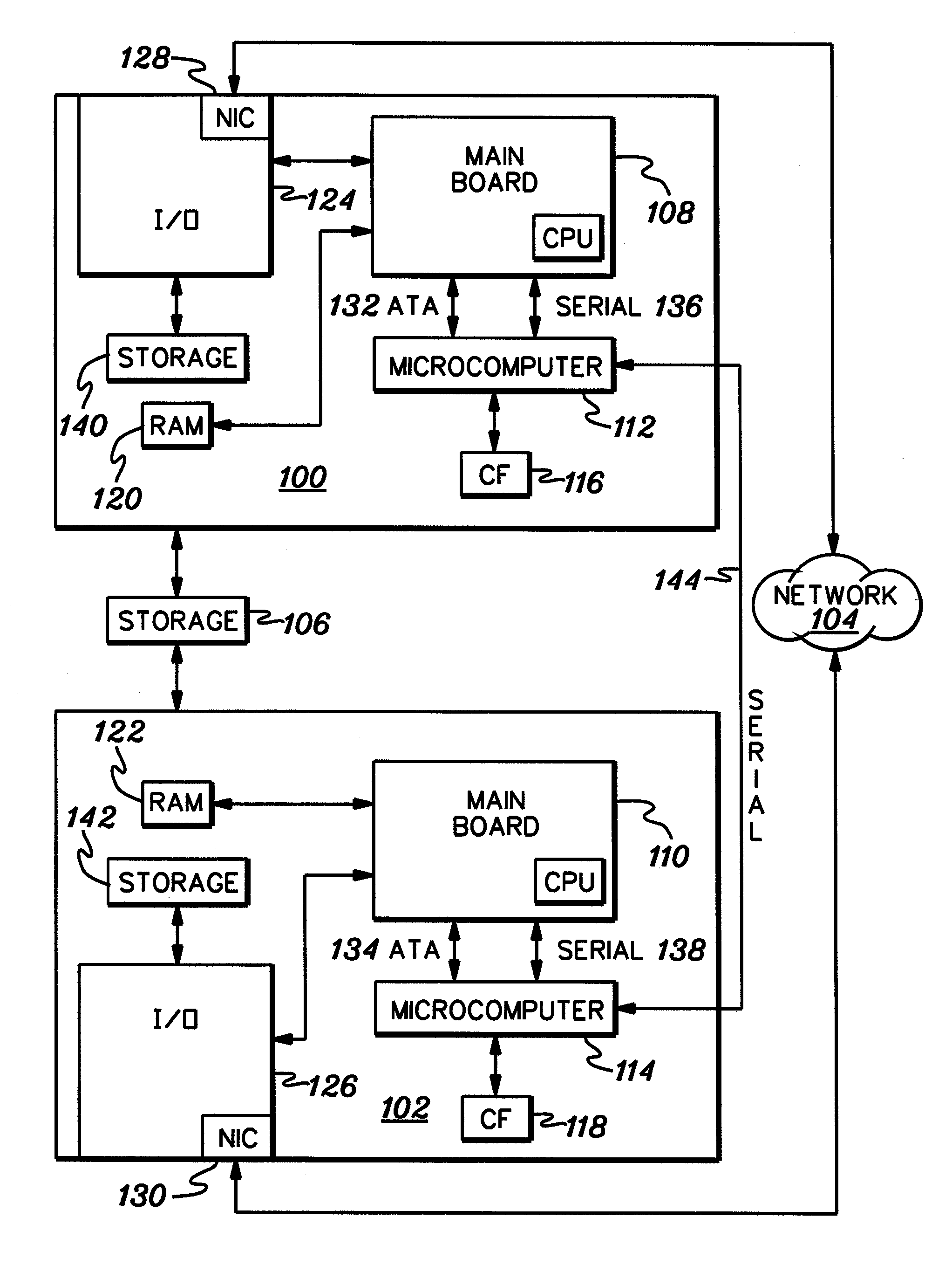
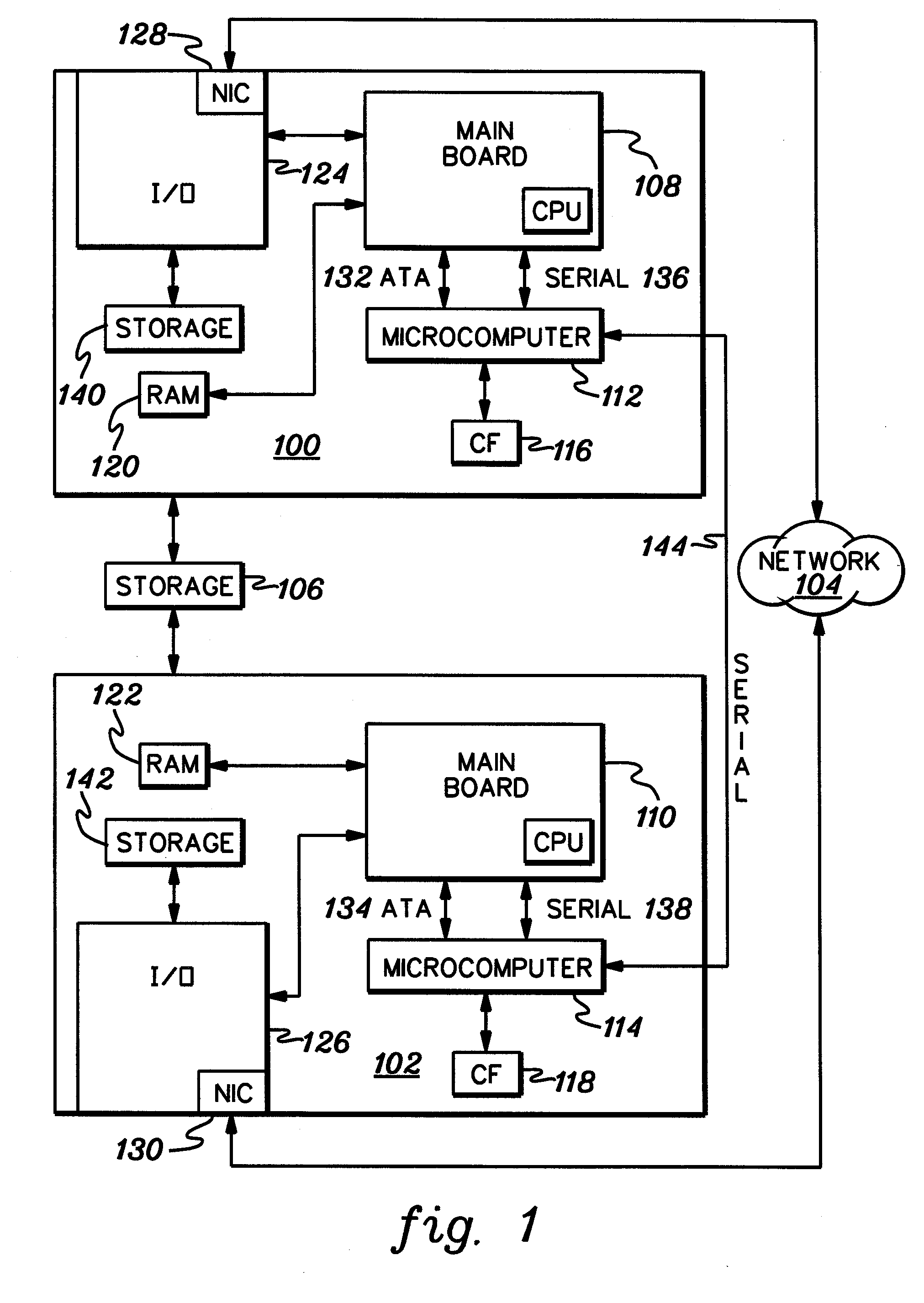
[0028]FIG. 1 is a simplified block diagram of two redundant network storage appliances 100 and 102 situated between a network 104 and network storage 106. The appliances are arranged to provide high availability of the network storage to the network. For example, the appliances can be arranged in an active-passive configuration. Each appliance comprises a main computing unit board (108, 110), an embedded microcomputer (112, 114), local nonvolatile storage (116, 118, 140, 142), RAM (120, 122) and input / output means (124, 126). Local nonvolatile storage 116, 118 is coupled to the respective microcomputer. The appliances are coupled to the network by, for example, gigabit Ethernet via network interface cards (128, 130). The computing units and their respective microcomputers are coupled for communication by, for example, a high volume connection (132, 134; e.g., ATA, SATA or high-speed USB (i.e., USB 2.0)) for boot image transfer, and a low-volume connection (136, 138; e.g., serial or ...


PUM


Abstract

A network storage appliance having a main computing unit is provided with an embedded microcomputer for monitoring startup and operation of the main computing unit. The microcomputer has the ability to restart, power down or power up the main computing unit if any corresponding predetermined conditions exist. Local nonvolatile storage holds the firmware for the main computing unit and configuration for the appliance. After loading the firmware and configuration to the main computing unit, the nonvolatile storage is electronically disconnected from the main computing unit. Where two such appliances are coupled for redundancy between the same network storage and the network, the embedded microcomputers are separately coupled for communication to allow for negotiating a restart of one of the main computing units under the direction of the other, or if any predetermined conditions occur.

Description

CROSS-REFERENCE TO RELATED APPLICATIONS [0001] This application claims priority under 35 U.S.C. §119 to U.S. Provisional Application No. 60 / 714,402, filed Sep. 6, 2005, which is herein incorporated by reference in its entirety. [0002] This application contains subject matter which is related to the subject matter of the following applications, each of which is assigned to the same assignee as this application and filed on the same day as this application. Each of the below listed applications is hereby incorporated herein by reference in its entirety: [0003] U.S. patent application Ser. No. ______, by Kirill Malkin, entitled “STORAGE RESOURCE SCAN” (Attorney Docket No. 2660.001A) [0004] U.S. patent application Ser. No. ______, by Malkin et al., entitled “REDUNDANT APPLIANCE CONFIGURATION REPOSITORY IN STANDARD HIERARCHICAL FORMAT” (Attorney Docket No. 2660.002A) [0005] U.S. patent application Ser. No. ______, by Kirill Malkin, entitled “BLOCK SNAPSHOTS OF iSCSI” (Attorney Docket No....

Claims


Application Information

Patent Timeline
IPC IPC(8): G06F15/173
CPCG06F11/0757G06F11/1417G06F11/2089H04L67/1097
Inventor MALKIN, KIRILLNEVEROVITCH, OLEG
Owner HEWLETT-PACKARD ENTERPRISE DEV LP
Learn More