
Method and apparatus for making fused silica

a technology of fused silica glass and process, applied in glass deposition burners, manufacturing tools, instruments, etc., can solve the problems of inhomogeneity in sintered glass, limited teaching in process and apparatus, etc., and achieve the effect of producing sintered fused silica glass of high purity and eas

Active Publication Date: 2007-06-14
CORNING INC
View PDF8 Cites 38 Cited by
  • Summary
  • Abstract
  • Description
  • Claims
  • Application Information

AI Technical Summary

Benefits of technology

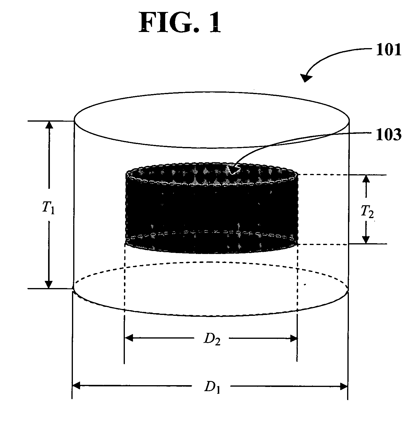
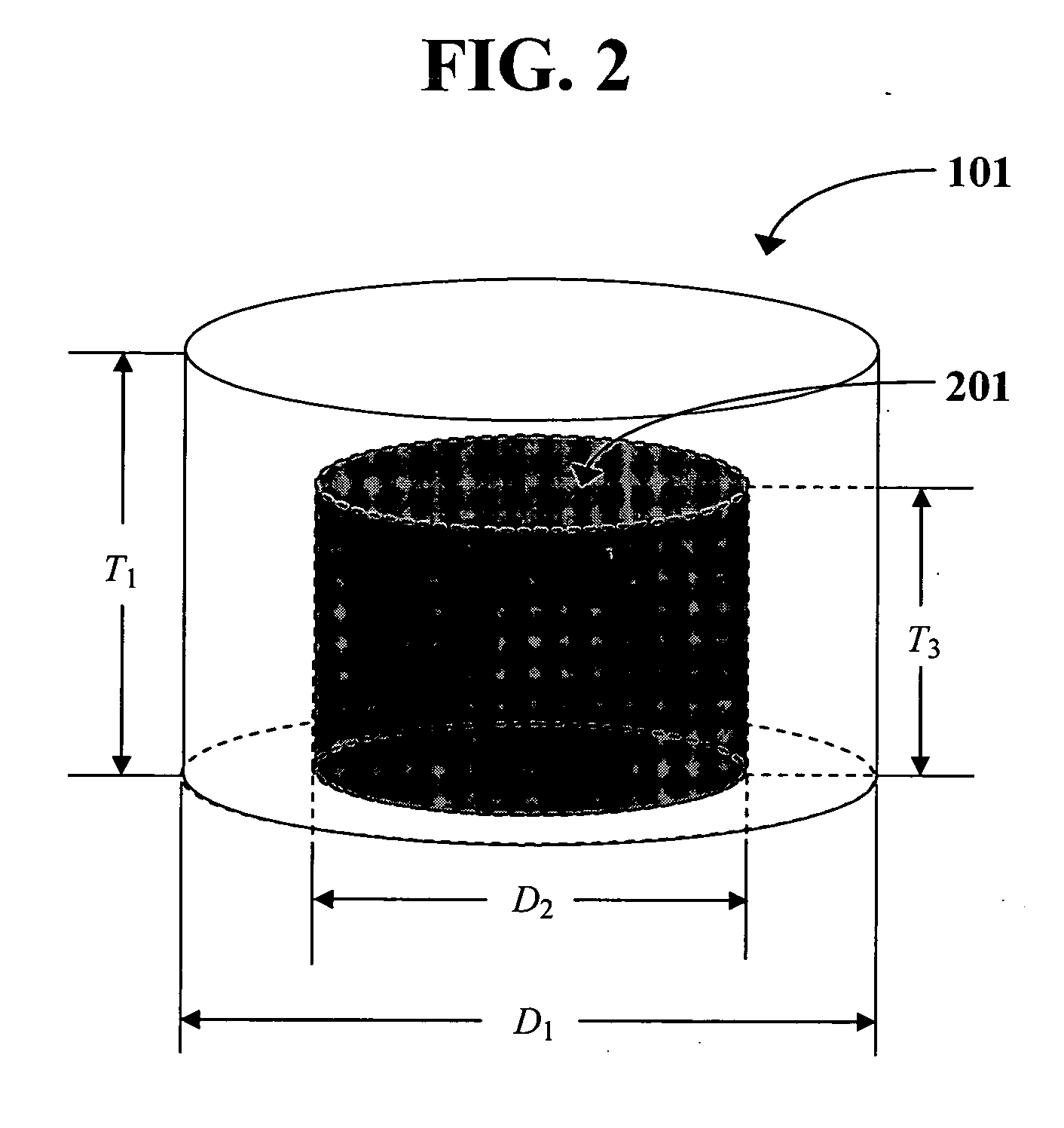
[0022] wherein in step (II), the soot-generating device is allowed to move relative to the deposition supporting surface, and the velocity of the soot-generating device relative to the deposition supporting surface is modulated such that in the identified cylinder, local soot density variation measured in a plane parallel to the bottom surface of the cylinder is low. In certain embodiments, the identified cylinder having a low local soot density variation has a diameter of at least 10 cm. In certain embodiments, the identified cylinder having a low local soot density variation has a diameter of at least 10 cm and a height of at least 5 cm. In certain embodiments, in step (II), the velocity of the soot-generating device relative to the deposition supporting surface is modulated such that in the identified cylinder, the soot preform exhibits a high OH concentration uniformity.
[0042] The present invention has the advantage of being capable of producing high purity sintered fused silica glass with ease. The soot preform produced by the process and apparatus of the present invention can be sintered into transparent glass in the apparatus of the present invention with desired physical properties without the need of further thermal reflow or homogenization.

Problems solved by technology

Because of the deposition techniques used, undesired property inhomogeneity in the sintered glass tend to exist, and post-sintering reforming of the glass are invariably required in order to produce the glass meeting the requirements of modern UV lithography.
However, the teaching in this reference of the process and apparatus is limited, especially with regard to the soot density variation of the soot preform produced therein.

Method used


Image

  • Method and apparatus for making fused silica
  • Method and apparatus for making fused silica
  • Method and apparatus for making fused silica

Examples


example

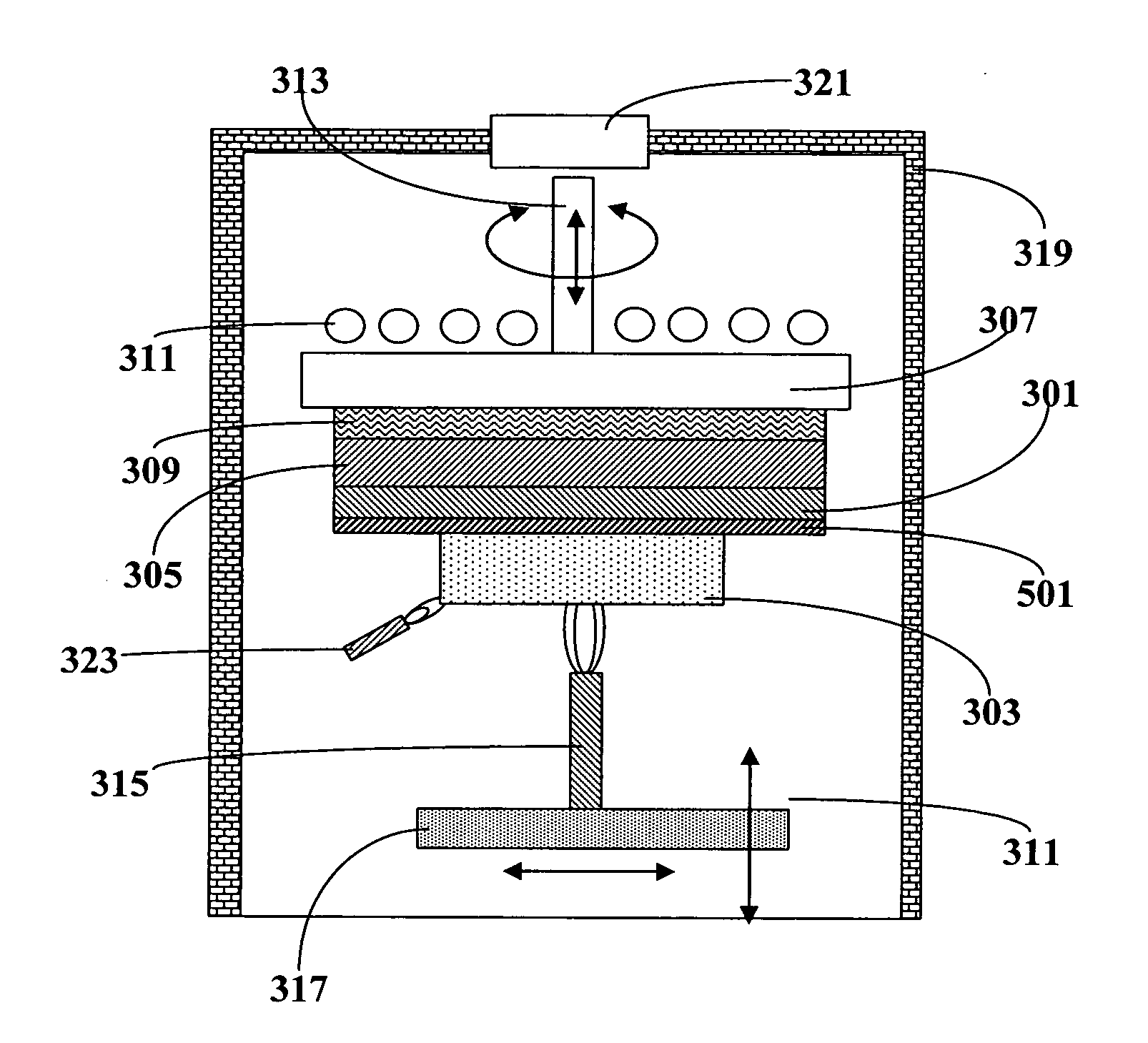
[0111] In this example, a silica soot preform was deposited in an apparatus schematically illustrated in FIG. 3. The induction heated heat source 305 was heated to about 700° C. before the soot deposition started. Heat source 305 was a graphite succeptor. The soot deposition substrate 301 is an about 6 mm (¼″) thick, 300 mm diameter high purity fused silica plate. The single burner 315 was allowed to oscillate linearly across the center of the deposition substrate 301. Feedstock to the burner included OMCTS, O2, and fuel. The silica soot generated in the flame was allowed to deposit on the upper surface of the deposition substrate 301 to form a soot preform. During the deposition, the stage 307, thus the heat source 305 and the deposition substrate 301, as well as the soot preform 303, rotate about the shaft 313. The burner was allowed to move up and down in order to maintain an essentially constant distance between the burner and the depositions substrate of about 7 inches (about 1...


PUM

PropertyMeasurementUnit
Temperatureaaaaaaaaaa

Abstract

Disclosed are process and apparatus for making high purity fused silica glass materials. The process involves depositing soot particles onto an essentially planar deposition supporting surface and modulation of motion of the soot-generating device relative to the deposition supporting surface to result in a low local soot density variation. The apparatus is designed to implement the planar deposition process. The invention makes it possible to produce fused silica glass without the use of potentially contaminating refractory bricks.

Description

FIELD OF THE INVENTION [0001] The present invention relates to process and apparatus for making doped or pure synthetic silica glass material. In particular, the present invention relates to process and apparatus for making doped or pure silica glass material involving planar deposition. The present invention is useful, for example, in making high purity and doped fused silica glass material for use as optical members in various applications, such as UV lithography devices. BACKGROUND OF THE INVENTION [0002] High purity or doped fused silica glass materials have found use in many modern optical systems. For example, state-of-the-art lithography devices in the semiconductor industry, especially those operating at deep UV and vacuum UV wavelengths, typically have refractive or reflective optical elements made from or based on high purity or doped fused silica glass materials. The high precision and resolution required for modern lithography devices in the production of very large scal...

Claims


Application Information

Patent Timeline
IPC IPC(8): C03B37/07C03B37/022C03C25/10
CPCC03B19/1423C03B19/1453C03B19/1476C03B2207/66C03C3/06C03C2201/23C03C2201/42
Inventor HAWTOF, DANIEL WARRENKELLEY, MICHAEL T.ROSETTIE, JOHN STEPHENSCHERMERHORN, ANDREW PAULSHAH, KASHYAP H.STONE, JOHN IIITANDON, PUSHKAR
Owner CORNING INC
Learn More