This helps you quickly interpret patents by identifying the three key elements:
Problems solved by technology
Method used
Benefits of technology
[0009] As applied to particular structures, such as tires, airfoils, pipes, etc., the conductive layers can be in the form of structural reinforcement layers, as well as passive layers that do not positively or negatively affect the overall structural integrity of the structure. Various sensing techniques can be utilized with the invention that are responsive to distortions in the first, second, and/or intermediate layers. In tire applications, such responsiveness can be used to monitor regular cyclic loading as the tire rotates, as well as irre
Problems solved by technology
However, in vessels subjected to fluids at relatively high pressures, once seepage occurs
Method used
Image
Click on the blue label to locate the original text in one second.
Reading with bidirectional positioning of images and text.
Examples
Embodiment Construction
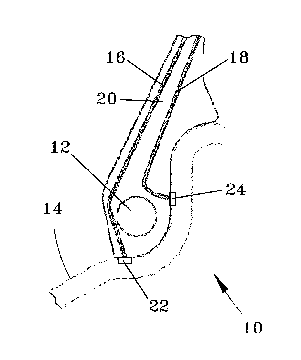
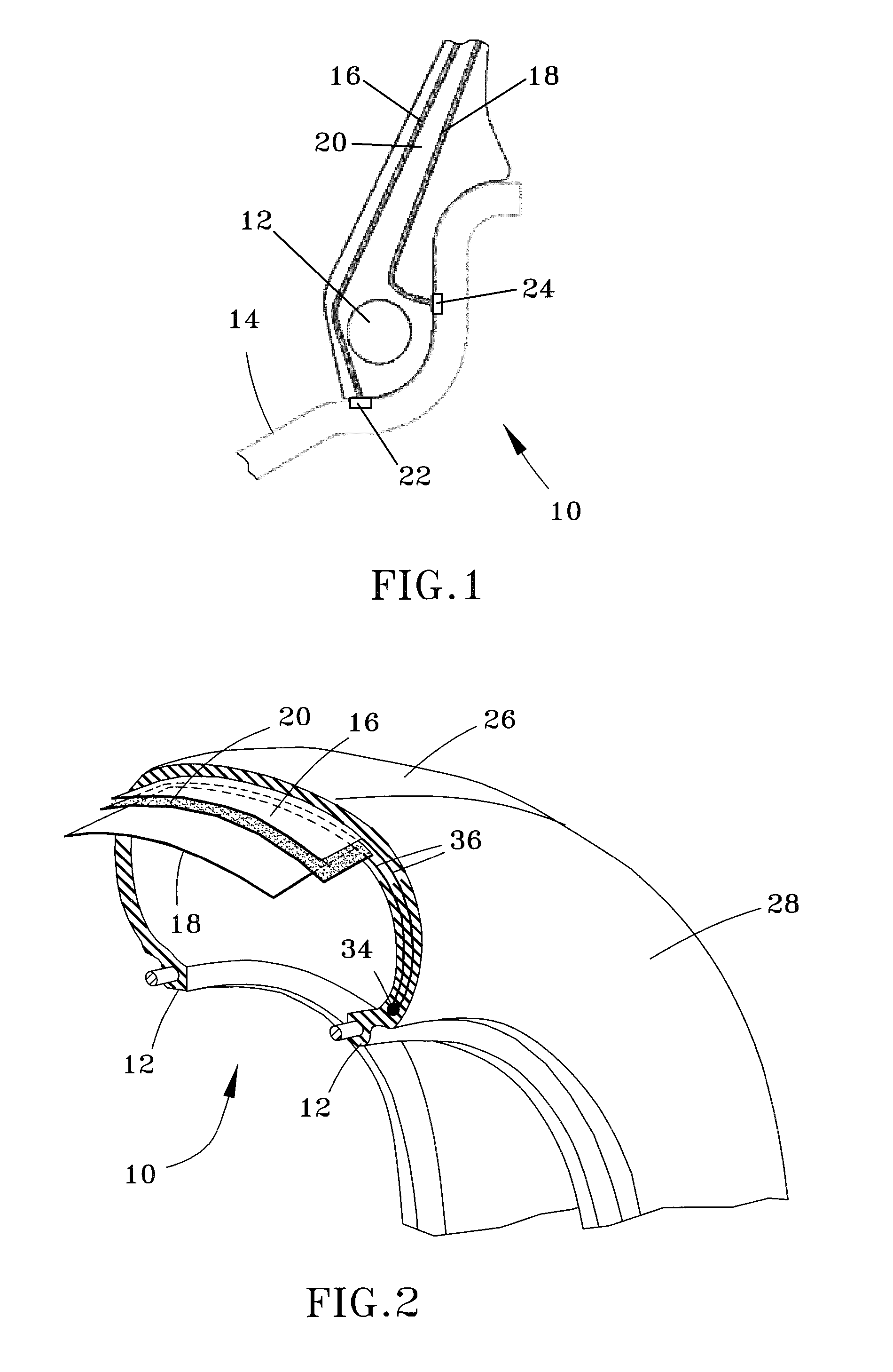
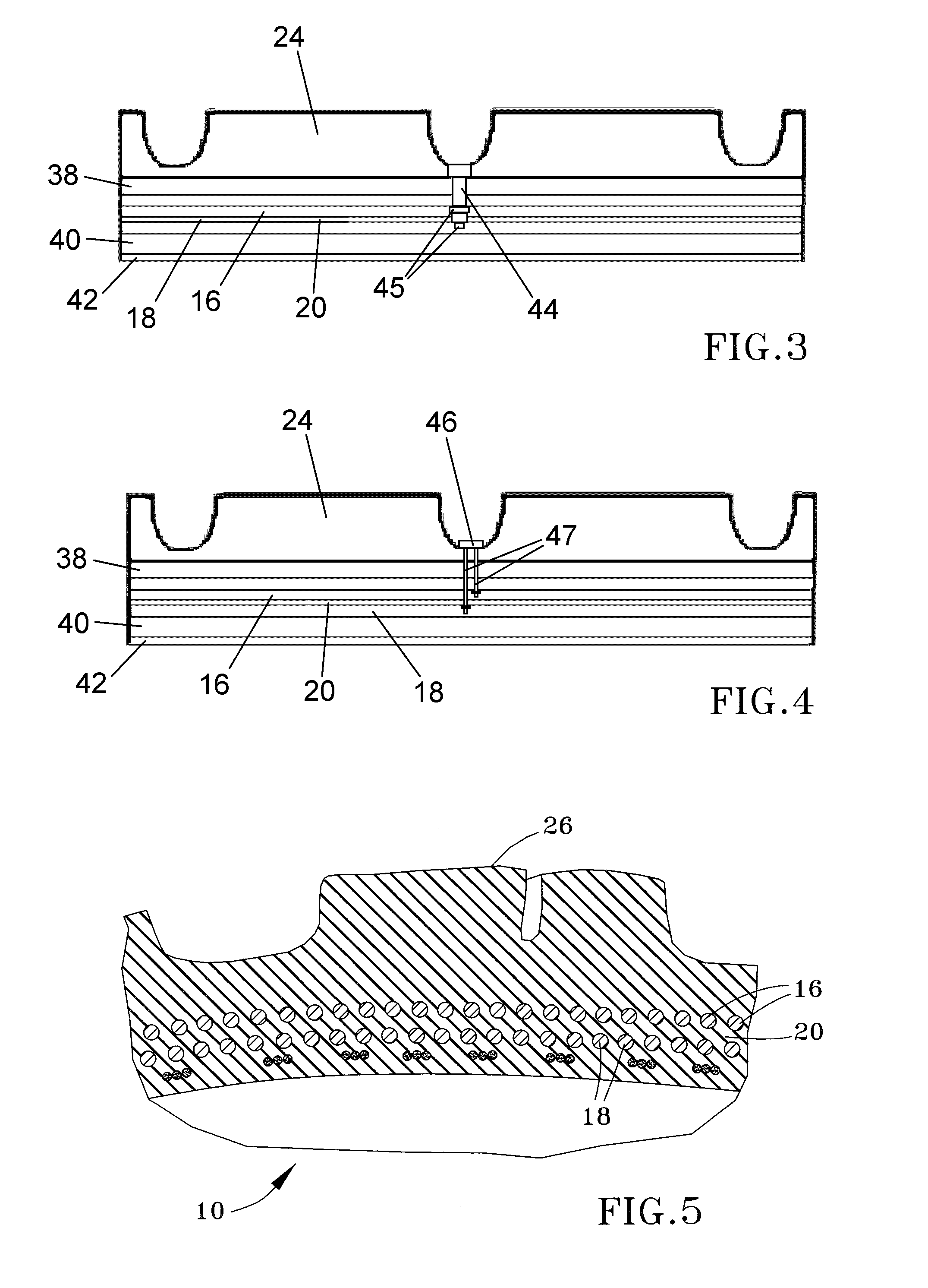
[0019] As represented in FIGS. 1 through 11, the present invention involves creating an electrical circuit within a manufactured structure subjected to high cyclical or intermittent forces, including but not limited to relatively high-pressure vessels such as tires, pipes, etc., and sensing changes in the electrical circuit that occur in response to transitory and permanent distortions of the structure. Such distortions can be the result of extrinsic and intrinsic sources, including extraneously applied forces and internal forces resulting from wear, fatigue, and other structural breakdowns within the structure. The electrical circuit contains conductive layers separated by dielectric, semiconductive, or resistive layers to form one or more capacitive or resistive elements by which changes in capacitance, resistance, or inductance can be sensed. The layers of the circuit are configured to enable sensing of an imminent fatigue failure, remaining life, and damage to the high-pressure ...
PUM
Abstract
A structure subjected to stresses that can lead to structural failure. The structure includes first and second conductive layers and an intermediate layer therebetween formed of a dielectric, semiconductive, or resistive material, such that the first, second, and intermediate layers form in combination an electrical element, namely, a capacitive or resistive element. The electrical element is located within the structure so as to be physically responsive to transitory and permanent distortions of the structure resulting from extrinsic and intrinsic sources. The structure further includes applying an electrical potential to at least one of the first and second conductive layers so as to generate an electrical signal from the electrical element, sensing changes in the electrical signal generated by the electrical element in response to the electrical element physically responding to the transitory and permanent distortions, and transmitting the changes in the electrical signal to a location remote from the structure.
Description
CROSS REFERENCE TO RELATED APPLICATIONS [0001] This application claims the benefit of U.S. Provisional Application No. 60 / 595,318, filed Jun. 22, 2005, and is a continuation-in-part patent application of co-pending U.S. patent application Ser. No. 11 / 276,500, filed Mar. 2, 2006, which claims the benefit of U.S. Provisional Application No. 60 / 658,932, filed Mar. 4, 2005. The contents of these prior applications are incorporated herein by reference.BACKGROUND OF THE INVENTION [0002] The present invention generally relates to structures subject to stresses that can lead to structural failure, such as structures that contact or contain static or flowing fluids, examples of which include tires, airfoils, and pipes of types used in mobile machinery, automotive, aerospace, manufacturing, and process equipment. More particularly, this invention relates to structures equipped with life-sensing means in terms of wear, fatigue, and / or other structural breakdowns within the structure, and means...
Claims
Application Information
Patent Timeline
Application Date:The date an application was filed.
Publication Date:The date a patent or application was officially published.
First Publication Date:The earliest publication date of a patent with the same application number.
Issue Date:Publication date of the patent grant document.
PCT Entry Date:The Entry date of PCT National Phase.
Estimated Expiry Date:The statutory expiry date of a patent right according to the Patent Law, and it is the longest term of protection that the patent right can achieve without the termination of the patent right due to other reasons(Term extension factor has been taken into account ).
Invalid Date:Actual expiry date is based on effective date or publication date of legal transaction data of invalid patent.