
Automatic SPT monitor

a monitor and automatic technology, applied in the field of subsurface exploration improvement methods, can solve the problems of no tool independent to check and verify the accuracy and quality of manual testing, destructive testing and drilling,

Active Publication Date: 2007-06-14
HONG KONG THE UNIV OF
View PDF6 Cites 24 Cited by
  • Summary
  • Abstract
  • Description
  • Claims
  • Application Information

AI Technical Summary

Benefits of technology

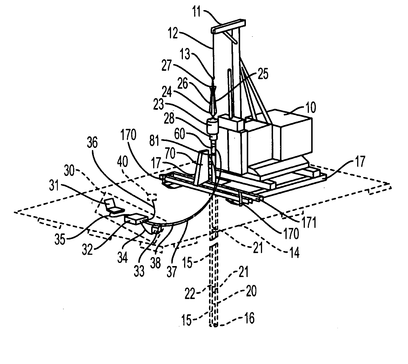
[0011] The field observation and issue of the manual operations and measurements of the conventional standard penetration test have led to the present invention for automation of the test measurements. The inserting process, the impact hammer and sampler penetrating process, and retrieval process are carried out sequentially in time sequence. A first object of the present invention is to provide an automatic digital SPT monitor for recording and evaluating the inserting process of the rods and sampler into a drill hole in real time, which enables the assessment and verification of the test depth and its commencement time. A second object of the present invention is to provide an automatic digital SPT monitor for recording and evaluating the impact hammer and sampler penetration process in real time, which is able to assess the soil resistance and more particularly the N-value and the associated hammer efficiency in accordance with a specification [in the present configuration, the specification is the Hong Kong Housing Authority specification]. A third object of the present invention is to provide an automatic digital SPT monitor for recording and evaluating the retrieval process of the rods and sampler from a drill hole in real time, which enables the assessment and verification of the test depth and its completion time.

Problems solved by technology

Furthermore, the testing and the drilling are destructive, non-repeatable and time consuming.
At present, there is no tool independently to check and verify the accuracy and quality of the manual test results.

Method used


Image

  • Automatic SPT monitor
  • Automatic SPT monitor
  • Automatic SPT monitor

Examples


Embodiment Construction

[0034] The present invention will be described in further detail by way of example with reference to the accompanying drawings. As shown in FIGS. 3 to 8, a digital SPT monitor 10 for measurement automation of standard penetration test according to the present invention comprises a micro-process controller 30, a tip depth transducer 40, a shock force transducer 60, and a shock penetration transducer 70. The micro-process controller 30 comprises a data logger 32, a battery 33, and a notebook computer 31. The data logger 32 uses a power supply cable 34 to attach the battery33 and uses a firewall cable 35 to communicate with the computer 31. The battery 33 is used to supply the small amount of power required for the data logger 32 and the notebook computer 31. The micro-process controller 30 further uses the first signal cable 36 to communicate with the tip depth transducer 40, the second signal cable 37 to communicate with the shock force transducer 50, and the third signal cable 38 wi...


PUM


Abstract

An apparatus is used with an impact hammer penetration assemble such as standard penetration test (SPT) in geotechnical engineering. The impact hammer penetration assembly comprises a penetration sample, a series of rods coupled together and an impact hammer apparatus. The drop of the hammer from a constant height hits the coupled rods and sampler in series and forces the sampler deeper into the ground. The apparatus includes a tip depth transducer and sampler to output a first electrical signal that is a function of the sampler tip position. A shock force transducer communicates the axial shock force in the rod to output a second electrical signal that is a function of the rod shock force and hammer blows. A shock penetration transducer communicates the movement of the coupled rods and sampler to output a third electrical signal that is a function of the sampler penetration due to the hammer blows. A micro-process controller monitors and processes the first, second and third signals in real time.

Description

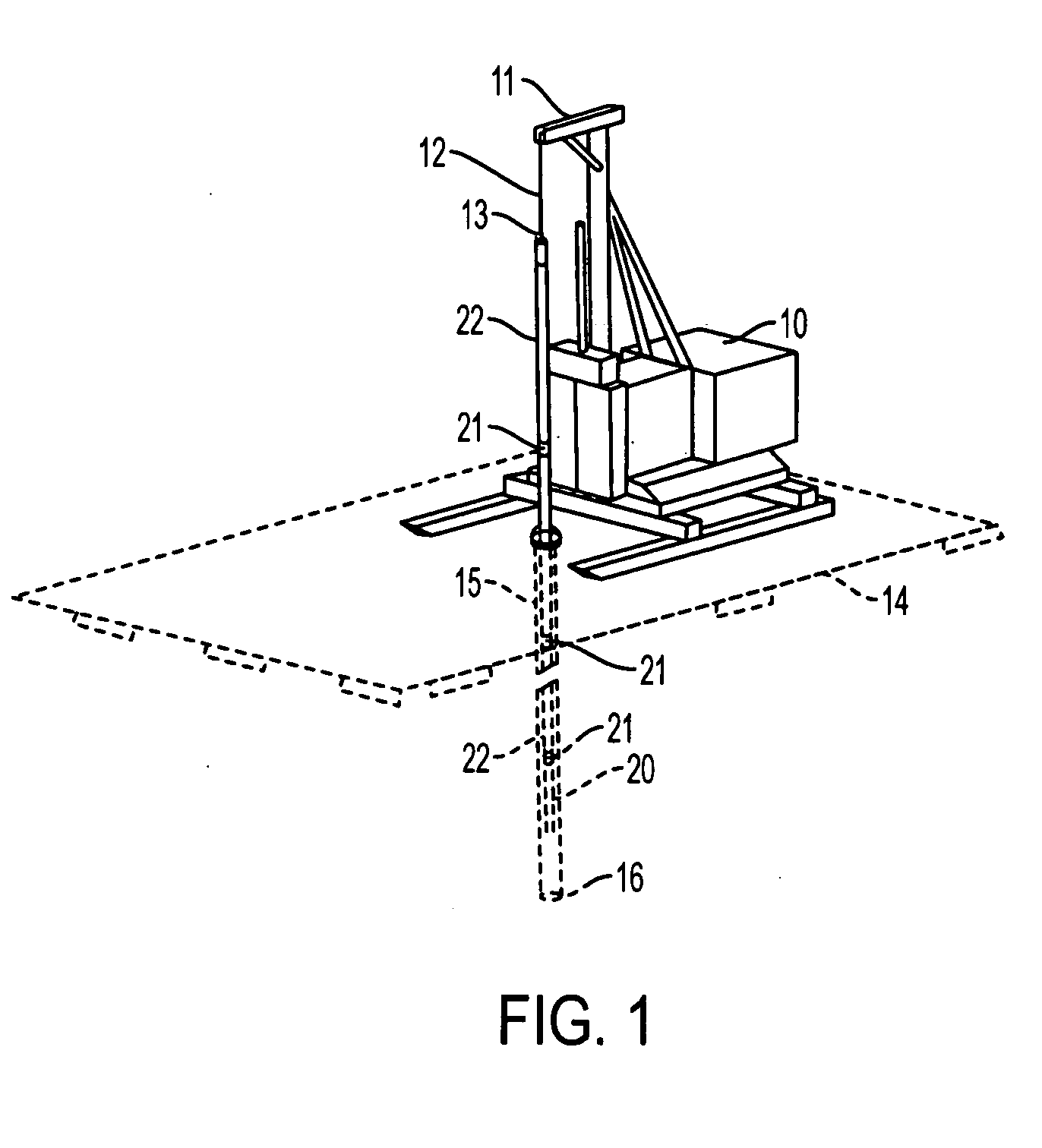
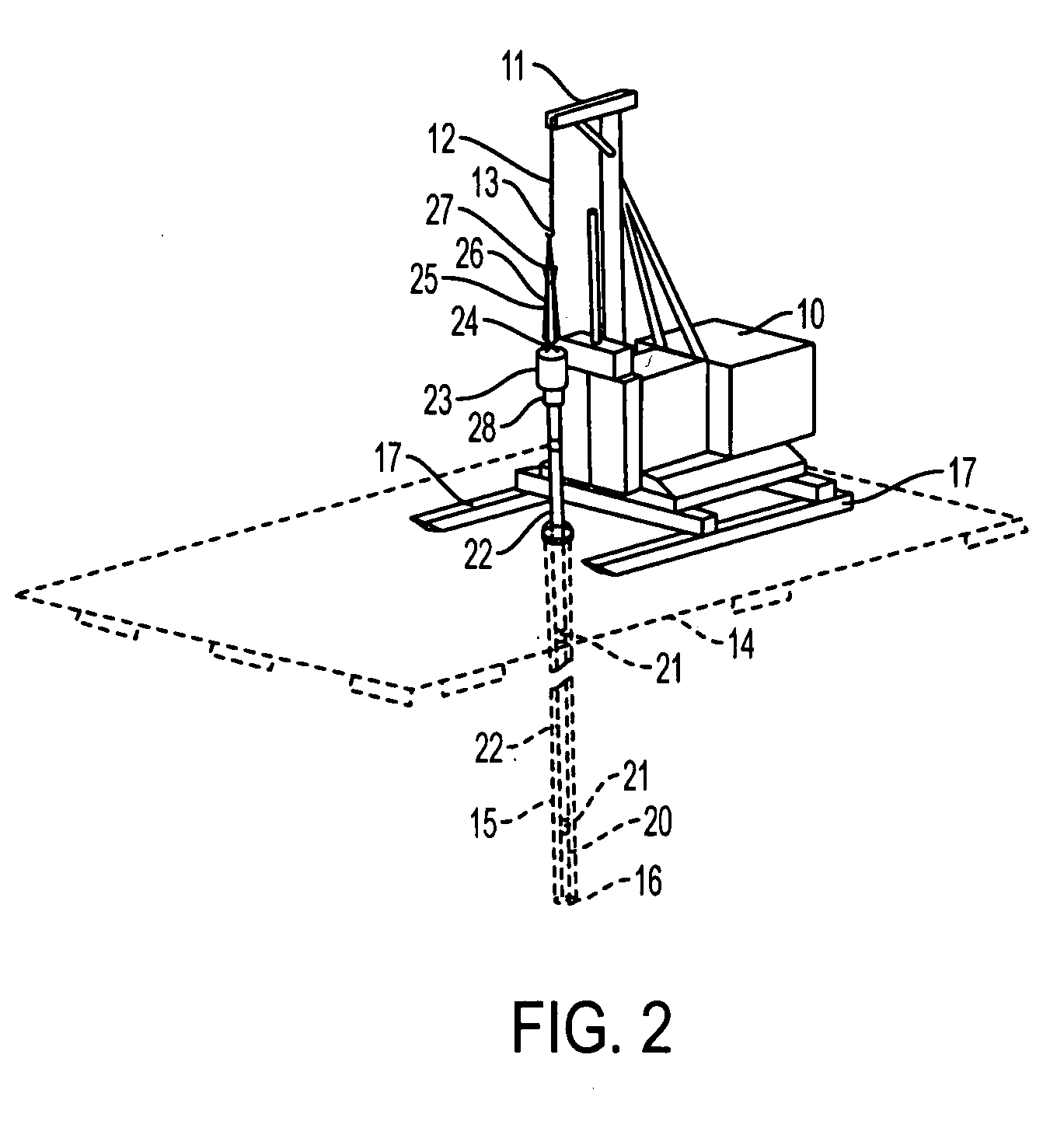
FIELD OF THE INVENTION [0001] This invention relates to improved methods for subsurface exploration, and more particularly to an automated apparatus and methods for performing the standard penetration test. BACKGROUND OF THE INVENTION [0002] The Standard Penetration Test (SPT) is an in-situ testing technique that drives a sampler into the ground at the bottom end of a drill hole (or borehole) during subsurface exploration. The test can yield a measure of the soil resistance to the penetration of the sampler under the impact of a free drop hammer from a constant height. [0003] There are two operators to conduct the test operations. As shown in FIGS. 1 and 2, the primary operator uses the power of the drilling rig and the steel wireline above the derrick to lift or drop the hoist hook. The secondary operator couples or decouples the hoist hook either with the top of a drill rod (FIG. 1) or with the steel chain of a impact hammer apparatus (FIG. 2). The impact hammer apparatus includes...

Claims


Application Information

Patent Timeline
IPC IPC(8): E21B11/02
CPCE02D1/022
Inventor YUE, ZHONG QILEE, CHACK FANLEE, PETER KAI KWONGTHAM, LESLIE GEORGE
Owner HONG KONG THE UNIV OF
Learn More