
AC Light Emitting Assembly and AC Light Emitting Device

a light-emitting assembly and light-emitting technology, which is applied in the direction of electroluminescent light sources, electric lighting sources, and use of semiconductors. it can solve the problems of low overall efficiency of wheatstone bridges and waste of significant light-emitting areas, so as to increase the overall efficiency, reduce the number and power consumption of rectifier components, and increase the overall efficiency

Active Publication Date: 2007-06-14
EPISTAR CORP
View PDF39 Cites 50 Cited by
  • Summary
  • Abstract
  • Description
  • Claims
  • Application Information

AI Technical Summary

Benefits of technology

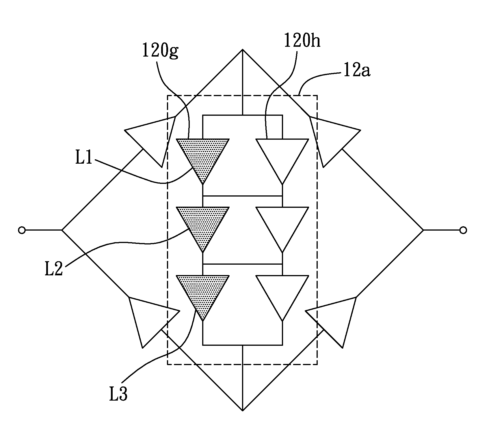
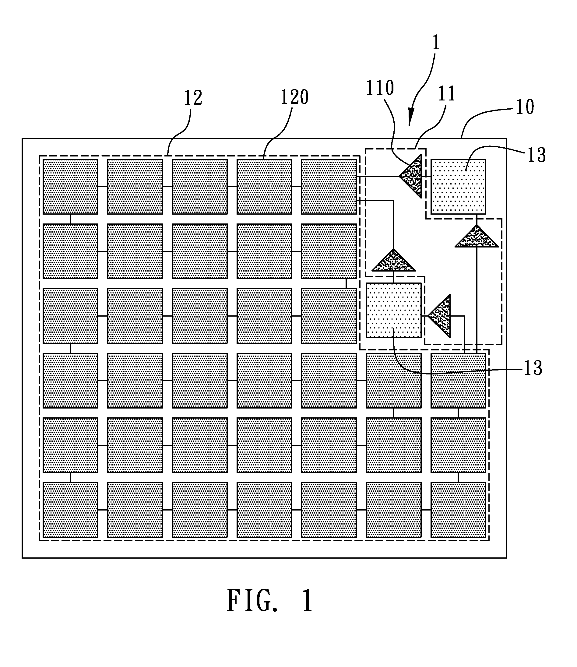
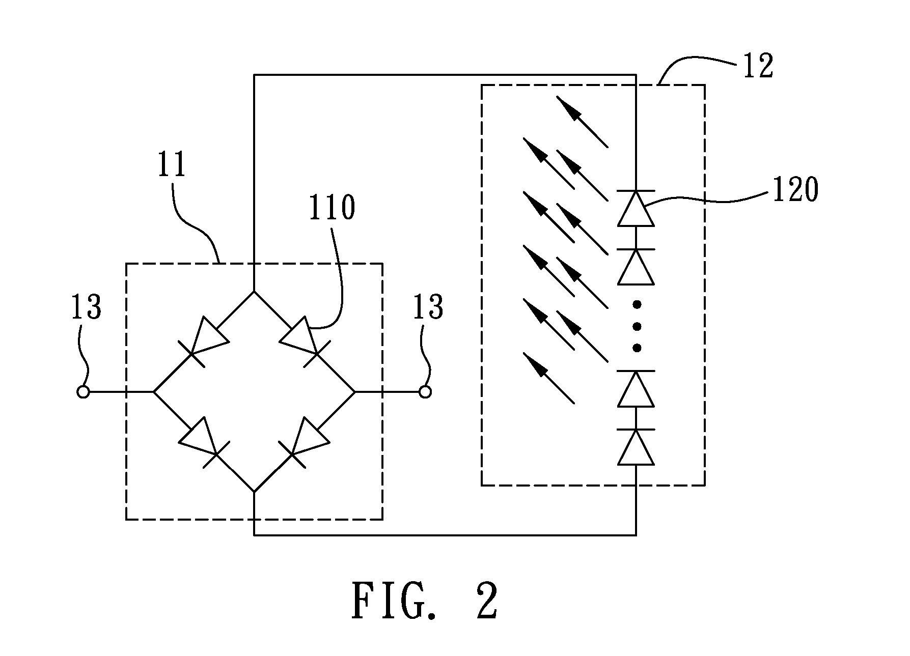
[0009] It is another objective of the present invention to provide an AC light emitting assembly and an AC light emitting device comprising the AC light emitting assembly, to reduce the power consumed by the rectifier components and increase the overall efficiency.
[0010] It is a further objective of the present invention to provide an AC light emitting assembly and an AC light emitting device comprising the AC light emitting assembly, to increase the light emitting area.
[0013] In contrast to the prior art, the present invention adopts a rectifier component having a high breakdown voltage and low forward voltage to rectify an AC signal into a DC signal, to reduce a number and power consumption of the rectifier components, increase the overall efficiency, and enlarge the overall light emitting area due to the saved space resulting from the reduction of the usage of the rectifier components.

Problems solved by technology

Further, the adoption of an AC LED as a rectifier component in the Wheatstone Bridge introduces two drawbacks.
In conclusion, the AC LEDs for rectification are far more than the AC LEDs for light emission, and the majority of input power will be consumed by the rectifier components and the Wheatstone Bridge has a low overall efficiency.
The other one of the drawbacks is that the Wheatstone Bridge, though having a larger light emitting area compared to the prior art, still have many rectifier components do not emit any light during a reverse biased voltage, and has a significant portion of the light emitting area wasted.

Method used


Image

  • AC Light Emitting Assembly and AC Light Emitting Device
  • AC Light Emitting Assembly and AC Light Emitting Device
  • AC Light Emitting Assembly and AC Light Emitting Device

Examples


Embodiment Construction

[0020] The following embodiments are described in sufficient detail to enable those skilled in the art to make and use the invention. It is to be understood that other embodiments would be evident based on the present disclosure, and that proves or mechanical changes may be made without departing from the scope of the present invention.

[0021] In the following description, numerous specific details are given to provide a thorough understanding of the invention. However, it will be apparent that the invention may be practiced without these specific details. In order to avoid obscuring the present invention, some well-known configurations and process steps are not disclosed in detail.

[0022] Likewise, the drawings showing embodiments of the structure are semi-diagrammatic and not to scale and, particularly, some of the dimensions are for the clarity of presentation and are shown greatly exaggerated in the drawings. Similarly, although the views in the drawings for ease of description ...


PUM


Abstract

An alternating current (AC) light emitting assembly and an AC light emitting device are disclosed. The AC light emitting assembly includes a substrate; a rectifier unit comprising a plurality of rectifier components arranged in a Wheatstone Bridge, for rectifying an AC signal into a direct current (DC) signal, each of the rectifier components having a high breakdown voltage and a low forward voltage; a light emitting unit electrically connected to the rectifier unit and comprising a plurality of light emitting components formed on the substrate, for emitting light when receiving the DC signal outputted by the rectifier unit; and two conductive electrodes electrically connected to the rectifier unit for receiving and transmitting the AC signal to the rectifier unit. The AC light emitting device includes two stacked and electrically connected AC light emitting assemblies.

Description

BACKGROUND OF THE INVENTION [0001] 1. Field of the Invention [0002] This invention relates to alternating current (AC) light emitting assemblies and AC light emitting devices, and more particularly, to an AC light emitting assembly and an AC light emitting device having the AC light emitting assembly, the AC light emitting assembly having a rectifier component for rectifying an AC signal into a direct current (DC) signal, the rectifier component having a high breakdown voltage and a low forward voltage. [0003] 2. Description of Related Art [0004] With the rapid development of opto-electronics technology, light emitting diode (LED) has becoming one of the most popular light emitting components in the market and has been applied to varieties of electronic fields. In particular, alternating current (AC) LED has been proclaimed by Seoul Semiconductor Co. and III-N Technology Co. in a product announcement symposium to be a global product in the near future. [0005] When receiving an AV si...

Claims


Application Information

Patent Timeline
Patent Type & Authority Applications(United States)
IPC IPC(8): H01L33/00
CPCH05B33/0803H05B33/0809H05B33/0821Y02B20/348H05B45/40Y02B20/30
Inventor YEN, HSI-HSUANCHI, JIM-YONGYEH, WEN-YUNGLEE, TING-CHILIN, MING-TEHUANG, SHENG-PAN
Owner EPISTAR CORP
Learn More