Position detecting device and synchronous motor driving device using the same

a technology of position detection and synchronous motor, which is applied in the direction of motor/generator/converter stopper, electronic commutator, dynamo-electric converter control, etc., can solve the problems of insatiable convenience in fabrication and maintenance, deterioration of detection resolution, and inability to meet the specifications of synchronous motors, etc., to eliminate the influence of temperature chang

Inactive Publication Date: 2007-06-14
HITACHI LTD
View PDF14 Cites 67 Cited by
  • Summary
  • Abstract
  • Description
  • Claims
  • Application Information

AI Technical Summary

Benefits of technology

[0007] As disclosed in Japanese Patent No. 3315847, in the field of the synchronous motor, there is known a position detecting method using an inexpensive Hall device as a position sensor which can not only detect a motor rotational position during rotat...

Problems solved by technology

For that reason, detection resolution is deteriorated and the accuracy in position detection becomes eventually insufficient, thus leading to a problem that specifications required for the synchronous motor cannot be satisfied.
Another problem is that, because a deviation of the mount position is not corrected, convenience in fabrication and maintenance is not satisfactory.
However, because the position error between the motor rotor (magnet position) and the position sensor is cor...

Method used


Image

  • Position detecting device and synchronous motor driving device using the same
  • Position detecting device and synchronous motor driving device using the same
  • Position detecting device and synchronous motor driving device using the same

Examples


first embodiment

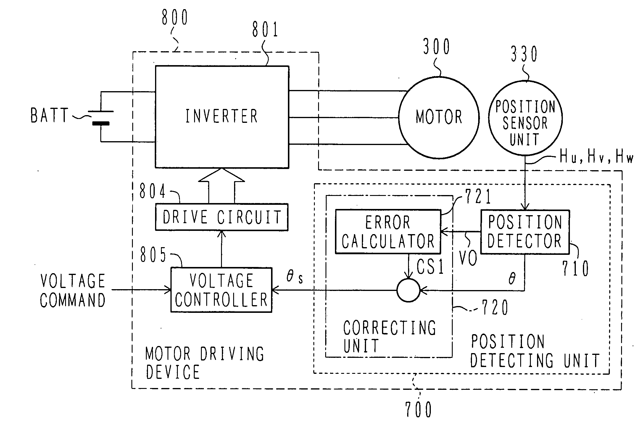
[0048] The construction of a synchronous motor driving device using a position detecting device according to the present invention will be described below with reference to FIGS. 1-9.

[0049] A description is first made of the construction of the synchronous motor driving device using the position detecting device according to this first embodiment with reference to FIG. 1.

[0050]FIG. 1 is a block diagram of the synchronous motor driving device using the position detecting device according to the first embodiment of the present invention.

[0051] A battery BATT serves as a DC voltage source for an inverter 801 in a motor driving device 800. A DC voltage is converted by the inverter 801 to a three-phase AC current with a variable voltage and a variable frequency, and the three-phase AC current is applied to a synchronous motor 300. A position sensor unit 330 is mounted to the synchronous motor 300 for controlling the phase of an applied three-phase AC voltage and the phase of an induced...

second embodiment

[0128] According to this second embodiment, as described above, since the gain error, the offset error, and the phase error can be corrected on the sensor signals with higher accuracy, the detection accuracy of the pole position can be further increased. It is hence possible to increase the accuracy in detecting the pole position of the motor which is used to perform quick acceleration and deceleration over the range from a zero speed to a high rotation speed.

[0129] The construction of a synchronous motor driving device using a position detecting device according to a third embodiment of the present invention will be described below with reference to FIGS. 12-14. Note that the basic construction of the position detecting device according to the third embodiment is the same as that shown in FIG. 10. Also, the basic construction of the synchronous motor driving device using the position detecting device according to the third embodiment is the same as that shown in FIG. 1.

[0130]FIG. ...

third embodiment

[0145] According to this third embodiment, as described above, since the gain error, the offset error, and the phase error can be corrected, the detection accuracy of the pole position can be increased. It is hence possible to increase the accuracy in detecting the pole position of the motor which is used to perform quick acceleration and deceleration over the range from a zero speed to a high rotation speed.

[0146] In addition, the temperature and the amount of the magnetic flux can also be detected using the amounts in changes of the gain error and the offset error. For example, the amount of change in the offset error can be determined as a temperature change and utilized for detecting the temperature. Also, the difference obtained by subtracting the gain error from a value corresponding to the temperature change can be determined as a change in the amount of the magnetic flux and utilized for detecting the amount of the magnetic flux. Therefore, temperature monitoring can be perf...


PUM


Abstract

A position detecting device which can increase accuracy in detecting the pole position of a motor used to perform quick acceleration and deceleration over the range from a zero speed to a high rotation speed, and a synchronous motor driving device using the position detecting device. A position detector detects basic-wave component signals in sensor signals and executes position calculation. A correcting unit calculates signal information representing at least one of a gain, an offset and a phase by a phase detector from the basic-wave component signals detected by an error calculator, and makes correction based on the calculated signal information such that a position detection error is zero.

Description

BACKGROUND OF THE INVENTION [0001] 1. Field of the Invention [0002] The present invention relates to a position detecting device for detecting a motor pole position and a synchronous motor driving device using the position detecting device. More particularly, the present invention relates to a position detecting device and a synchronous motor driving device using the same, which are suitably used to perform acceleration and deceleration over the range from a zero speed (stopped state) to a high rotation speed. [0003] 2. Description of the Related Art [0004] As one of devices for driving a synchronous motor (hereinafter referred to simply as a “motor”), there is known a type of driving the motor by using a position detecting device which detects a rotor pole position. Here, the term “position detecting device” means a device, such as a resolver or an absolute rotary encoder, which can not only detect a motor rotational angle during rotation, but also determine an absolute position in...

Claims


Application Information

Patent Timeline
IPC IPC(8): H02P1/46H02P27/00H02P6/06H02P6/16H02P6/08
CPCH02P6/10H02P6/16H02P2209/07G01D5/2046
Inventor AJIMA, TOSHIYUKIMIYAZAKI, HIDEKISASAKI, MASATAKAFURUYAMA, BUNJISUWA, TOKIHITO
Owner HITACHI LTD
Why Eureka
Try Eureka