Position Detecting Device and Synchronous Motor Driving Device Using the Same
a technology of synchronous motors and detection devices, applied in the direction of motor/generator/converter stoppers, electronic commutators, dynamo-electric converter control, etc., can solve the problems of deteriorating detection resolution, insatiable specifications for synchronous motors, and inconvenient fabrication and maintenance. achieve the effect of high accuracy
- Summary
- Abstract
- Description
- Claims
- Application Information
AI Technical Summary
Benefits of technology
Problems solved by technology
Method used
Image
Examples
first embodiment
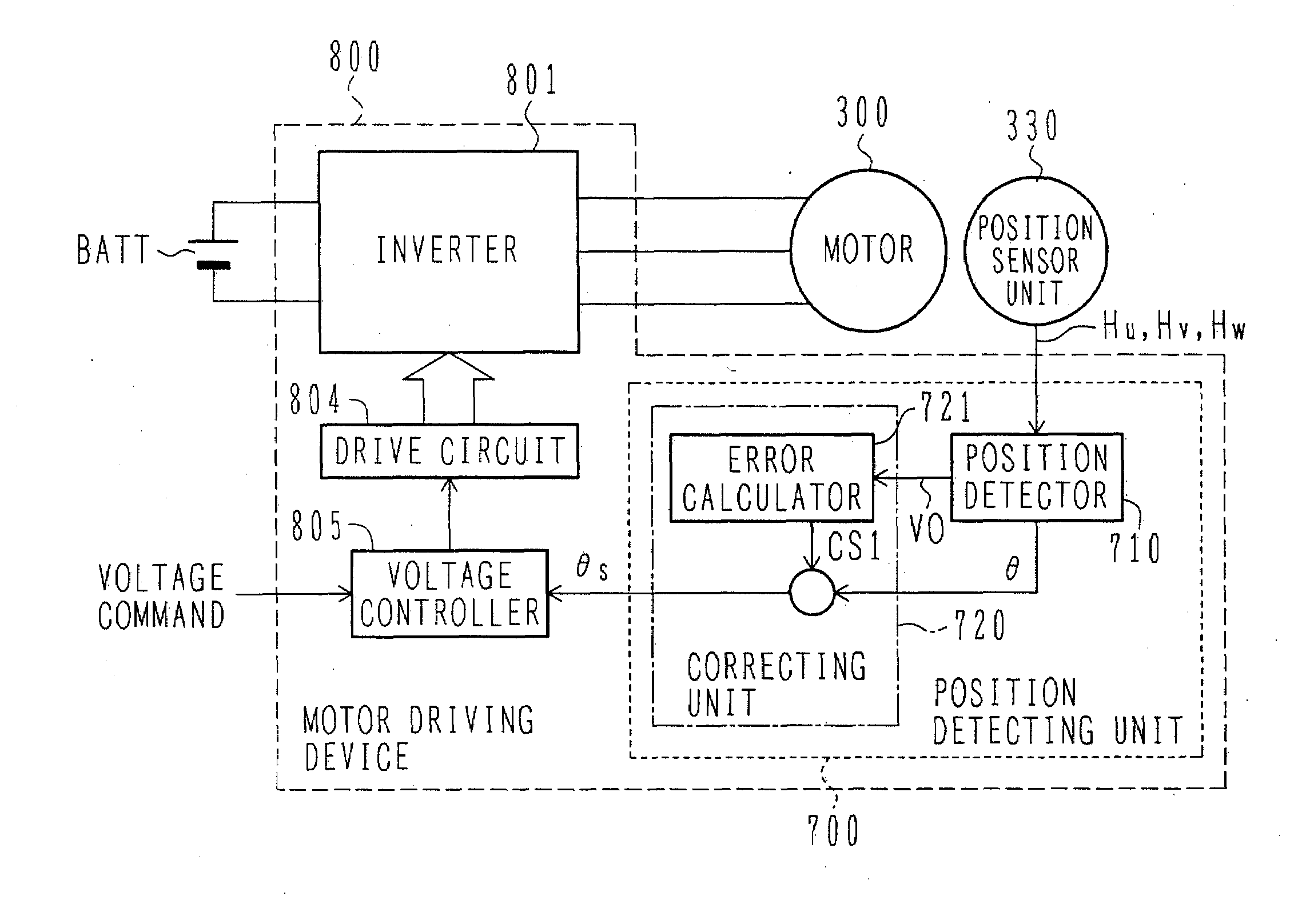
[0049]The construction of a synchronous motor driving device using a position detecting device according to the present invention will be described below with reference to FIGS. 1-9.
[0050]A description is first made of the construction of the synchronous motor driving device using the position detecting device according to this first embodiment with reference to FIG. 1.
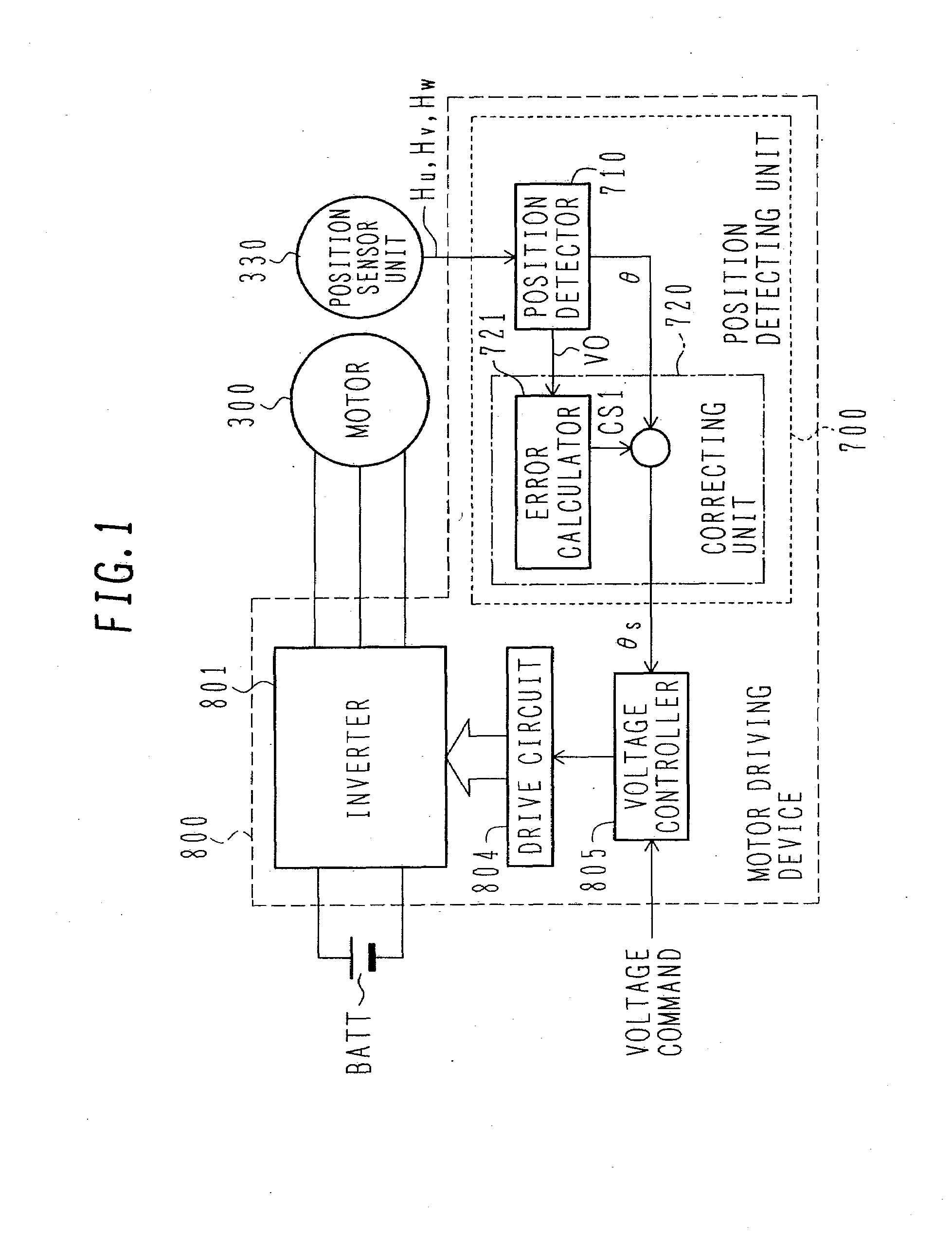
[0051]FIG. 1 is a block diagram of the synchronous motor driving device using the position detecting device according to the first embodiment of the present invention.
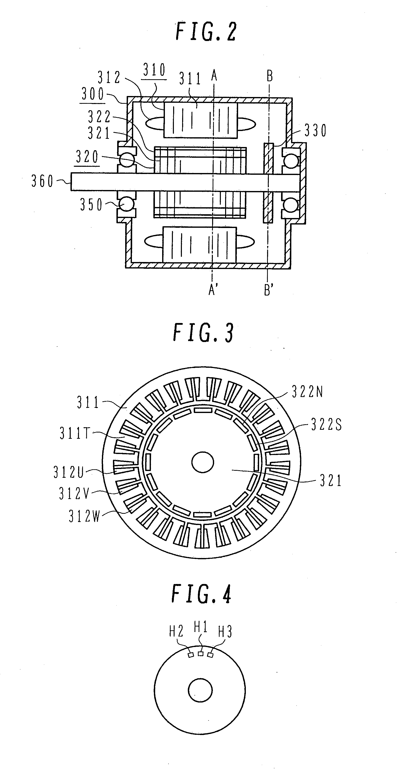
[0052]A battery BATT serves as a DC voltage source for an inverter 801 in a motor driving device 800. A DC voltage is converted by the inverter 801 to a three-phase AC current with a variable voltage and a variable frequency, and the three-phase AC current is applied to a synchronous motor 300. A position sensor unit 330 is mounted to the synchronous motor 300 for controlling the phase of an applied three-phase AC voltage and the phase of an induced volt...
second embodiment
[0129]According to this second embodiment, as described above, since the gain error, the offset error, and the phase error can be corrected on the sensor signals with higher accuracy, the detection accuracy of the pole position can be further increased. It is hence possible to increase the accuracy in detecting the pole position of the motor which is used to perform quick acceleration and deceleration over the range from a zero speed to a high rotation speed.
[0130]The construction of a synchronous motor driving device using a position detecting device according to a third embodiment of the present invention will be described below with reference to FIGS. 12-14. Note that the basic construction of the position detecting device according to the third embodiment is the same as that shown in FIG. 10. Also, the basic construction of the synchronous motor driving device using the position detecting device according to the third embodiment is the same as that shown in FIG. 1.
[0131]FIG. 12 ...
third embodiment
[0146]According to this third embodiment, as described above, since the gain error, the offset error, and the phase error can be corrected, the detection accuracy of the pole position can be increased. It is hence possible to increase the accuracy in detecting the pole position of the motor which is used to perform quick acceleration and deceleration over the range from a zero speed to a high rotation speed.
[0147]In addition, the temperature and the amount of the magnetic flux can also be detected using the amounts in changes of the gain error and the offset error. For example, the amount of change in the offset error can be determined as a temperature change and utilized for detecting the temperature. Also, the difference obtained by subtracting the gain error from a value corresponding to the temperature change can be determined as a change in the amount of the magnetic flux and utilized for detecting the amount of the magnetic flux. Therefore, temperature monitoring can be perfor...
PUM
 Abstract
Description
Claims
Application Information
 - R&D
- Intellectual Property
- Life Sciences
- Materials
- Tech Scout
- Unparalleled Data Quality
- Higher Quality Content
- 60% Fewer Hallucinations
Browse by: Latest US Patents, China's latest patents, Technical Efficacy Thesaurus, Application Domain, Technology Topic, Popular Technical Reports.
© 2025 PatSnap. All rights reserved.Legal|Privacy policy|Modern Slavery Act Transparency Statement|Sitemap|About US| Contact US: help@patsnap.com


