Voltage-controlled oscillator, transmitter, and receiver

a voltage-controlled oscillator and transmitter technology, applied in the direction of oscillator stabilization, oscillator generator, transmission, etc., can solve the problems of noise increase, phase noise characteristic deterioration, noise deterioration, etc., and achieve good phase noise characteristic, easy to downsize

a voltage-controlled oscillator and transmitter technology, applied in the direction of oscillator stabilization, oscillator generator, transmission, etc., can solve the problems of noise increase, phase noise characteristic deterioration, noise deterioration, etc., and achieve good phase noise characteristic, easy to downsize

US20070132524A1Inactive Publication Date: 2007-06-14SHARP KK

Image

  • Voltage-controlled oscillator, transmitter, and receiver
  • Voltage-controlled oscillator, transmitter, and receiver
  • Voltage-controlled oscillator, transmitter, and receiver

Examples


Embodiment Construction

[0036] The following will describe an embodiment of the present invention in reference to FIGS. 1-4.

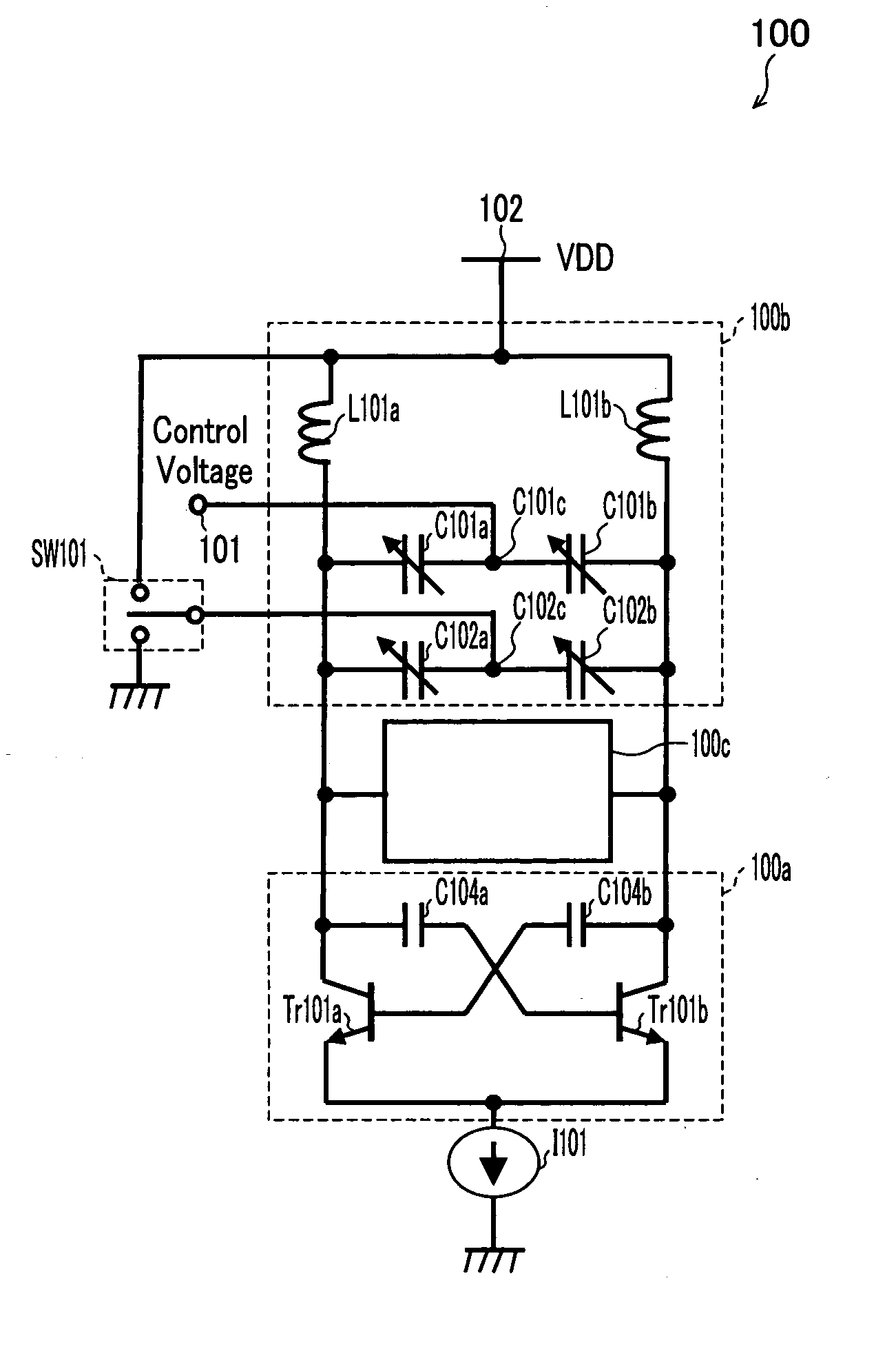
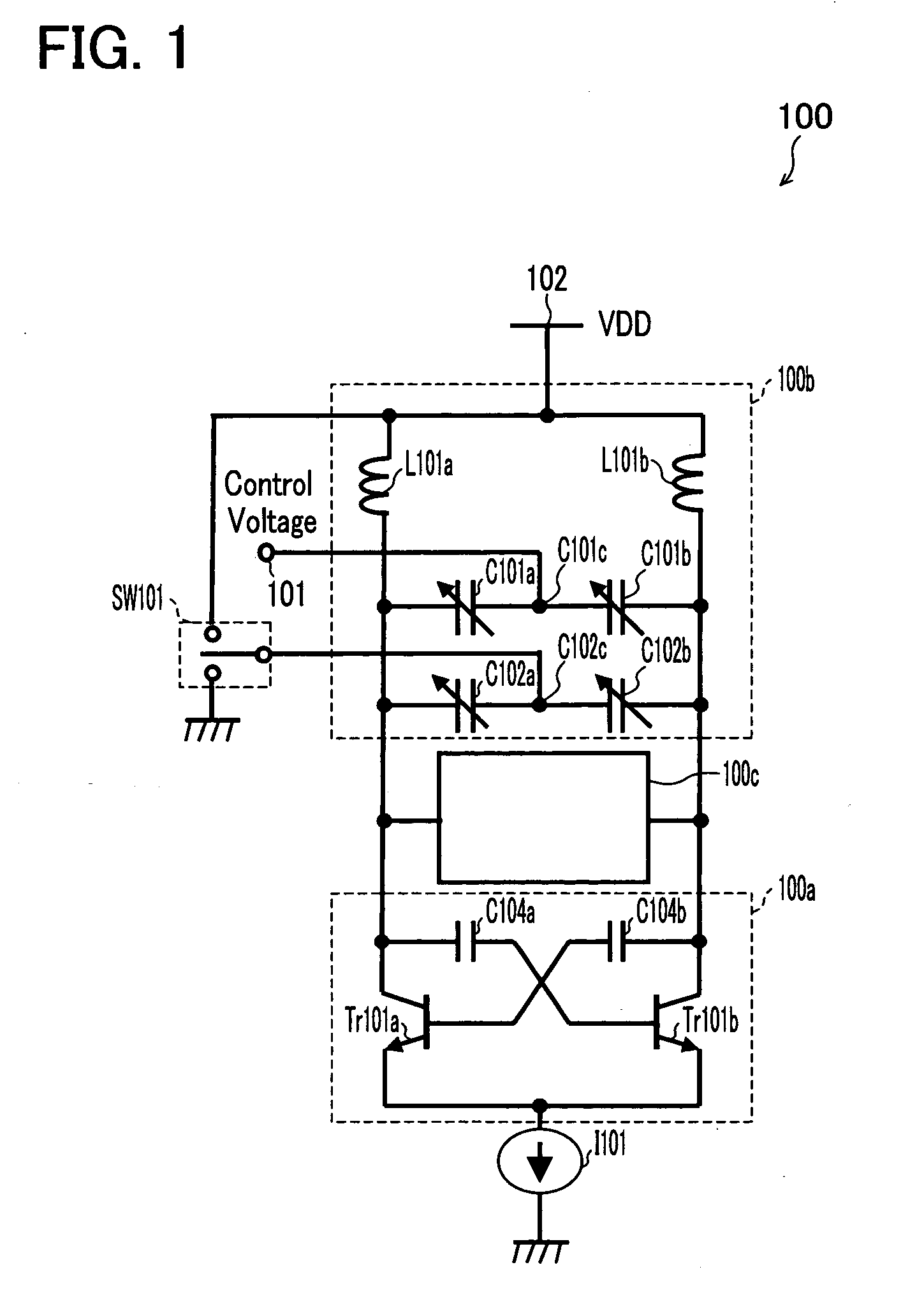
[0037] First, a voltage-controlled oscillator 100 of the embodiment of the present invention will be described in reference to FIG. 1. FIG. 1 is a circuit block diagram which outlines the voltage-controlled oscillator 100. The voltage-controlled oscillator 100 basically includes an amplifier circuit 100a, a resonance circuit 100b, and a resonance frequency correction circuit 100c, so that oscillation is performed by feeding the output of the amplifier 100a back to the amplifier circuit 100a via the resonance circuit 100b.

[0038] The amplifier circuit 100a of the voltage control circuit 100 includes a pair of transistors Tr101a and Tr101b. These transistors Tr101a and Tr101b constitute a differential pair. As shown in FIG. 1, the emitters of the transistors Tr101a and Tr101b are grounded via a shared current source 101. The collector of the transistor Tr101a is connected to the base o...


PUM


Abstract

A voltage-controlled oscillator includes (i) a first variable-capacity element, (ii) a resonance circuit whose resonance frequency changes in accordance with a control voltage applied to the first variable-capacity element, (iii) a second variable-capacity element connected in parallel with the first variable-capacity element, (iv) resonance frequency range switching means which switches the variation range of the resonance frequency of the resonance circuit by switching the capacity of the second variable-capacity element, and (v) a resonance frequency correction circuit which corrects the resonance frequency in such a manner as to prevent the ratio between resonance frequencies before and after the switching of the variation range from depending on the control voltage.

Description

[0001] This Nonprovisional application claims priority under 35 U.S.C. § 119(a) on Patent Application No. 358268 / 2005 filed in Japan on Dec. 12, 2005, the entire contents of which are hereby incorporated by reference. FIELD OF THE INVENTION [0002] The present invention relates to a voltage-controlled oscillator, and particularly to a voltage-controlled oscillator which can switch and control the variation range of oscillating frequencies. BACKGROUND OF THE INVENTION [0003] In recent years voltage-controlled oscillators (VCOs), which can control oscillating frequencies by applying a control voltage, have widely been used for, for example, local oscillators of wireless transmitter-receivers. Such a voltage-controlled oscillator is required to be highly stable, have low phase noise, generate low noise, or the like. However, since the range of oscillating frequencies of a wireless transmitter-receiver is wide, the aforesaid requirements cannot be satisfied by a single voltage-controlled...

Claims


Application Information

Patent Timeline
14 Jun 2007
Publication
US20070132524A1
IPC
H03B5/12; H04B1/04; H04B1/26; H04B1/40
CPC
H03B2201/0266; H03B5/1231; H03B5/1215; H03B5/1265
Inventors
KISHINO, YUSUKE