Linear FM radar

a radar and linear fm technology, applied in the field of radar and ground penetrating radar imaging methods, can solve the problems of not having recognized this source of error, no solution proposed in conventional radar implementations, unpredictable frequency of return echo signals, etc., and achieves less bulky, fine radar details, and easy maneuverability.

Active Publication Date: 2007-06-14
LANDRAY TECH
View PDF19 Cites 68 Cited by
  • Summary
  • Abstract
  • Description
  • Claims
  • Application Information

AI Technical Summary

Benefits of technology

[0011] An advantage of the present invention is that a digital linear-FM ground-penetrating radar is provided that is less bulky, easier to maneuver, and provides finer radar details compared to multi-antenna fixed arrays.
[0012] Another advantage of the present invention is that a means is provided that can collect radar data at intervals smaller than the size of the antenna both along and perpendicular to the direction of motion of the radar along the ground because the radar antenna is also moved in a circle.
[0013] A further advantage of the present invention is that a digital linear-FM ground-penetrating radar is provided that can provide sharp 3-D subsurface images over a substantial swath width in a single pass of the radar.
[0014] A still further advantage of the present invention is that the digital linear-FM ground-penetrating radar is produces higher spatial resolution images due to the set of phase and amplitude compensations that are applied.
[0015] Another advantage of the present invention is that a digital linear-FM ground-penetrating radar is provided that is more efficient and has lower power consumption due to digitizing the radar data in the frequency domain rather than the time domain.

Problems solved by technology

In FM-radar, the frequency of the return echo signal is unpredictable because it depends on the unknown range to the target.
Prior art has neither recognized this source of error nor have there been any solutions proposed in conventional radar implementations.

Method used


Image

  • Linear FM radar
  • Linear FM radar
  • Linear FM radar

Examples


Embodiment Construction

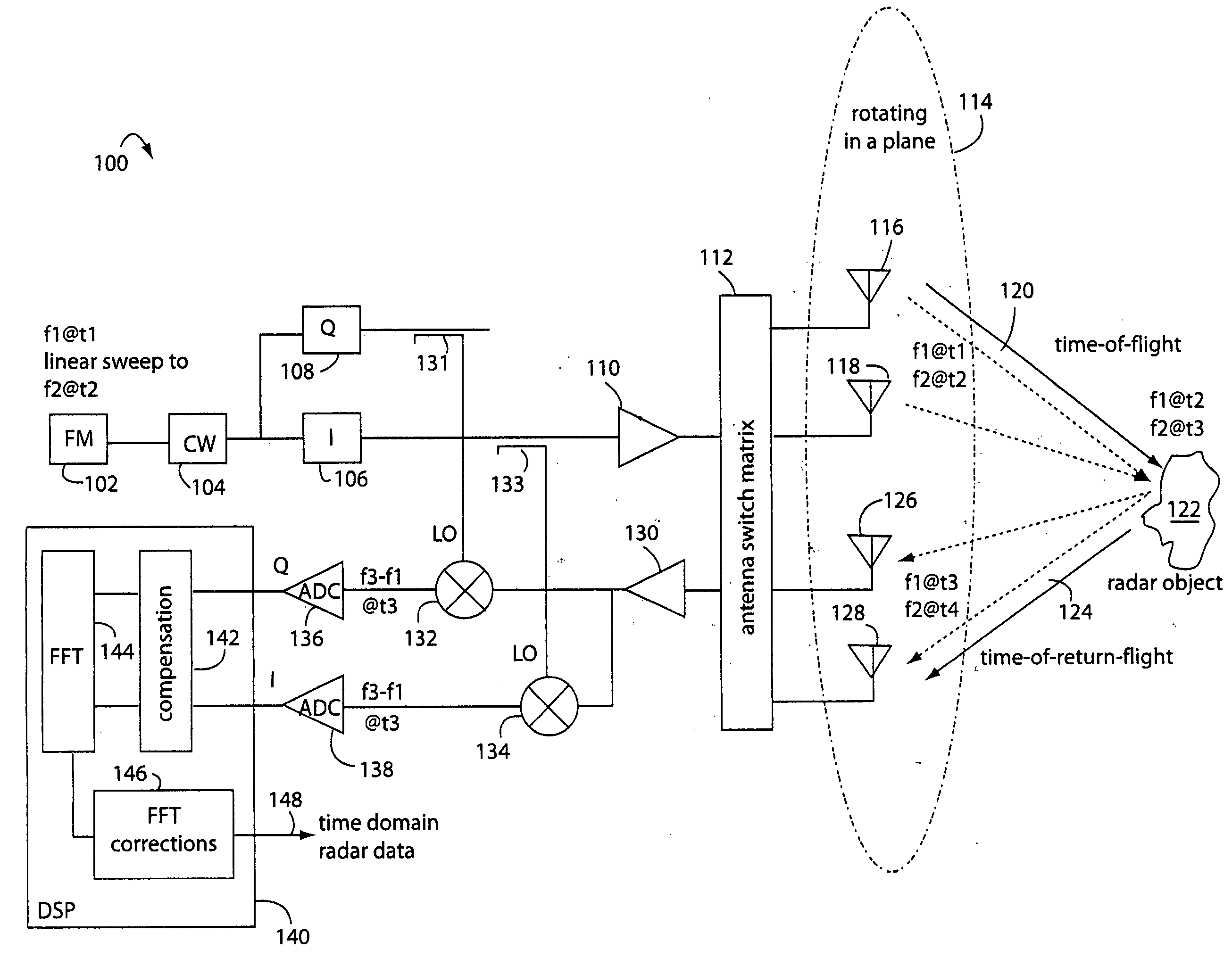
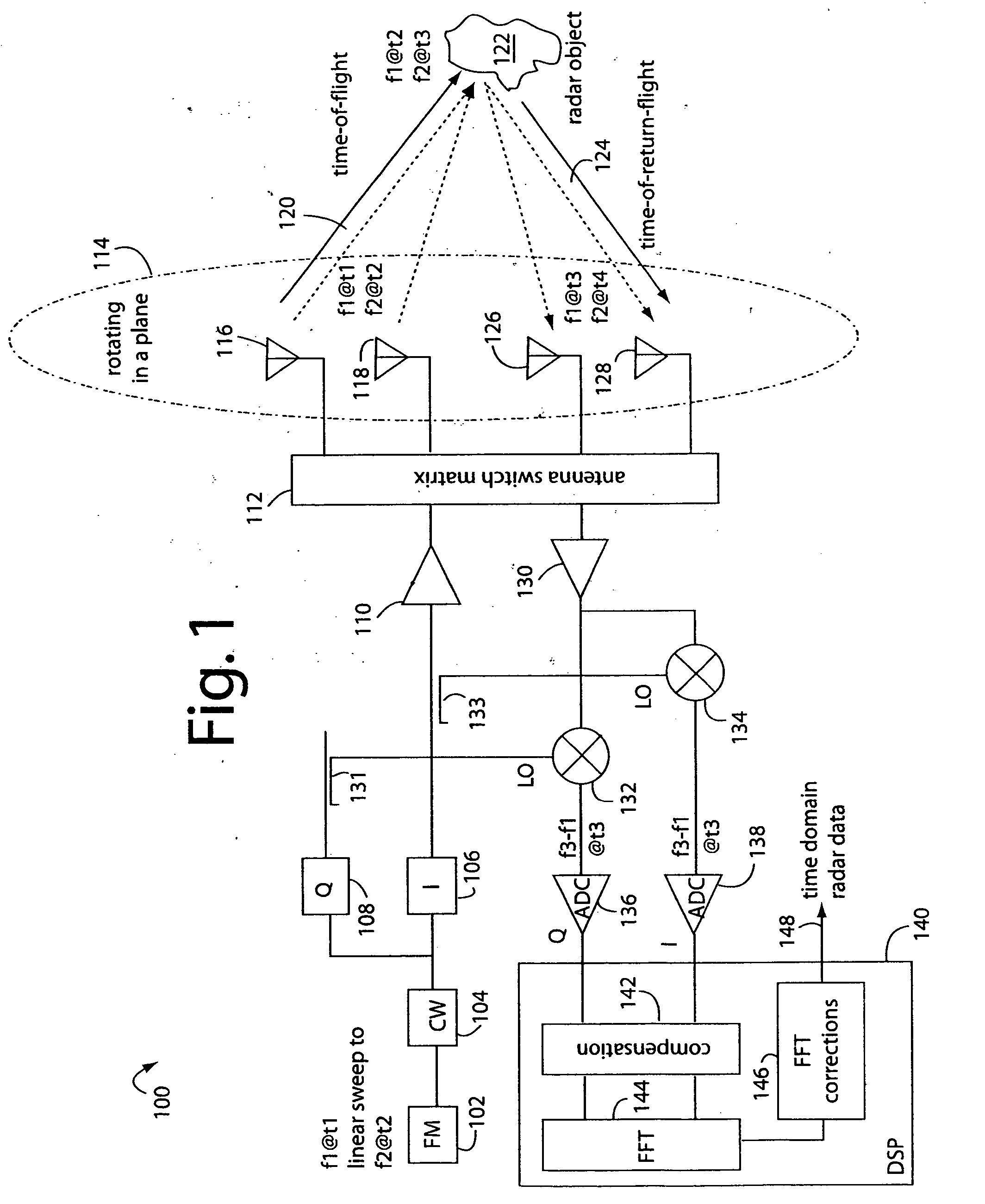
[0023]FIG. 1 illustrates an FM-CW radar system embodiment of the present invention, and is referred to herein by the general reference numeral 100. The radar system 100 comprises a frequency modulator (FM) 102 that causes a continuous wave (CW) generator 104 to linearly sweep through a band of frequencies. For example, at a time-1 (t1) the transmitter frequency from CW generator 104 will be frequency-1 (f1). At a time-2 (t2), the transmitter frequency will slew up to a frequency-2 (f2). And at a time-3 (t3), the transmitter frequency will slew further to a frequency-3 (f3). An in-phase (I) unit 106 digitally produces an I-signal, and a quadrature-phase (Q) unit 108 digitally produces a Q-signal 90-degrees shifted in phase. The I-signal is amplified by a power amplifier 110 before being selectively switched through an antenna matrix 112 to a rotating antenna array 114.

[0024] The rotating antenna array 114 allows, e.g., transmitting antennas 116 and 118, to radiate their signals from...


PUM


Abstract

A FM-CW radar system comprises a frequency modulated continuous wave digital generator that produces both in-phase (I) and quadrature-phase (Q) outputs to orthogonally oriented transmitter antennas. A linearly polarized beam is output from a switched antenna array that allows a variety of I-and-Q pairs of bowtie antennas to be alternately connected to the transmitter and receiver. The receiver inputs I-and-Q signals from another bowtie antenna in the array and mixes these with samples from the transmitter. Such synchronous detection produces I-and-Q beat frequency products that are sampled by dual analog-to-digital converters (ADC's). The digital samples receive four kinds of compensation, including frequency-and-phase, wiring delay, and fast Fourier transform (FFT). The compensated samples are then digitally converted by an FFT-unit into time-domain signals. Such can then be processed conventionally for range information to the target that has returned the FM-CW echo signal.

Description

BACKGROUND OF THE INVENTION [0001] 1. Field of the Invention [0002] The present invention relates to radar and ground penetrating radar imaging methods, and more particularly to radars that linearly sweep through frequencies and synchronously detect return signals affected by time-of-flight delays to target objects. [0003] 2. Description of Related Art [0004] Frequency modulated (FM) continuous wave (CW) radars transmit a sweep frequency that is mixed with a return echo to produce a beat frequency. The beat frequency output from the mixer is a function of both how fast the CW output is sweeping in frequency and how far the return echo had to travel from the transmitter to the target and back to the receiver. A faster FM sweep of the CW signal increases the scale of the beat frequency product. Given a linear sweep, e.g., a sawtooth, and a fixed distance to the radar target, then the beat frequency will be a steady tone. The bandwidth of that tone determines the resolution of the rada...

Claims


Application Information

Patent Timeline
Patent Type & Authority Applications(United States)
IPC IPC(8): G01S13/88G01V3/12G01S7/40
CPCG01S7/024G01S7/034G01S13/34G01S13/885H01Q1/3233H01Q3/04H01Q9/28
Inventor BECKNER, FREDERICK L.
Owner LANDRAY TECH
Why Eureka
Try Eureka