Adaptive network and method

a technology of adaptive network and network array, applied in the field of adaptive network, can solve the problems of inability to facilitate nighttime surveillance with more expensive night vision equipment, inhibit rapid reconfiguration, and high cost of video camera and lighting installation, so as to facilitate the re-structuring of perimeter sensors and promote rapid coordinate positioning.

Active Publication Date: 2007-06-14
ACEINNA TRANSDUCER SYST CO LTD
View PDF41 Cites 78 Cited by
  • Summary
  • Abstract
  • Description
  • Claims
  • Application Information

AI Technical Summary

Benefits of technology

[0007] In accordance with one embodiment of the present invention, a plurality of individual mobile transceiver modules may be deployed around the perimeter of an installation to be secured in order to sense and transmit information about activity within a vicinity of a transceiver module. Each module wirelessly communicates its own sensory data and identity information to one or more similar adjacent modules, and can relay data signals received from one or more adjacent modules to other adjacent modules in the formation of a distributed self-adaptive wireless network that may communicate with a central computer. Such interaction of adjacent modules obviates power wiring and signal cabling and the need for an electromagnetic survey of an area to be secured, and promotes convenient re-structuring of perimeter sensors as desired without complications of re-assembling hard-wired sensors and monitors. In addition, interactions of adjacent modules establish verification of an intrusion event that is distinguishable from false detection events, and promote rapid coordinate location of the intrusion event for follow-up by computer-controlled video surveillance or other alarm responses. Multiple modules are deployed within and about a secured area to automatically configure a wirelessly-interconnected network of addressed modules that extends the range of individual radio transmission and identifies addressed locations in and about the secured area at which disabling or intrusion events occur. Frequency-shifting schemes among the modules inhibit jamming or unauthorized disabling of the network, and new modules may be added to the network in synchronism with prevailing reference frequency. The network of modules may be expanded about individual base stations that each operate on separate reference frequencies that are shifted synchronously in non-overlapping relationship. In this way, modules operating in one network associated with one base station are segregated from interaction with modules operating in another network, even within sufficient proximity to directly communicate if not so inhibited by distinctive reference frequencies. Modules are fabricated to include unique ID codes and ability to operate on a common set of different reference frequencies in order to be compatibly operable in an assembled network of such modules. Individual modules within the entire network may be reprogrammed from the base station over the radio links between modules.

Problems solved by technology

Additionally, lighting may be installed about the area, or more-expensive night-vision equipment may be required to facilitate nighttime surveillance.
These tactics:are commonly expensive for video cameras and lighting installations and for continuing labor expenses associated with continuous shifts of attendant personnel.
However, such sophisticated systems nevertheless commonly require permanent installations of sensors, lighting and cameras with associated power and cabling that inhibit rapid reconfiguration, and that increase vulnerability to breakdown due to severing of wiring and cabling, or to unreliable operations upon exposure to severe weather conditions.
Since these networks may include perhaps hundreds of individual modules, manually loading the code can be time consuming and labor intensive for a field support person going to each module and via a portable processor transferring the new code to each module and then having each module restart with the new code.
However, over long sleep intervals conditions for interactive communications may have changed.

Method used


Image

  • Adaptive network and method
  • Adaptive network and method
  • Adaptive network and method

Examples


Embodiment Construction

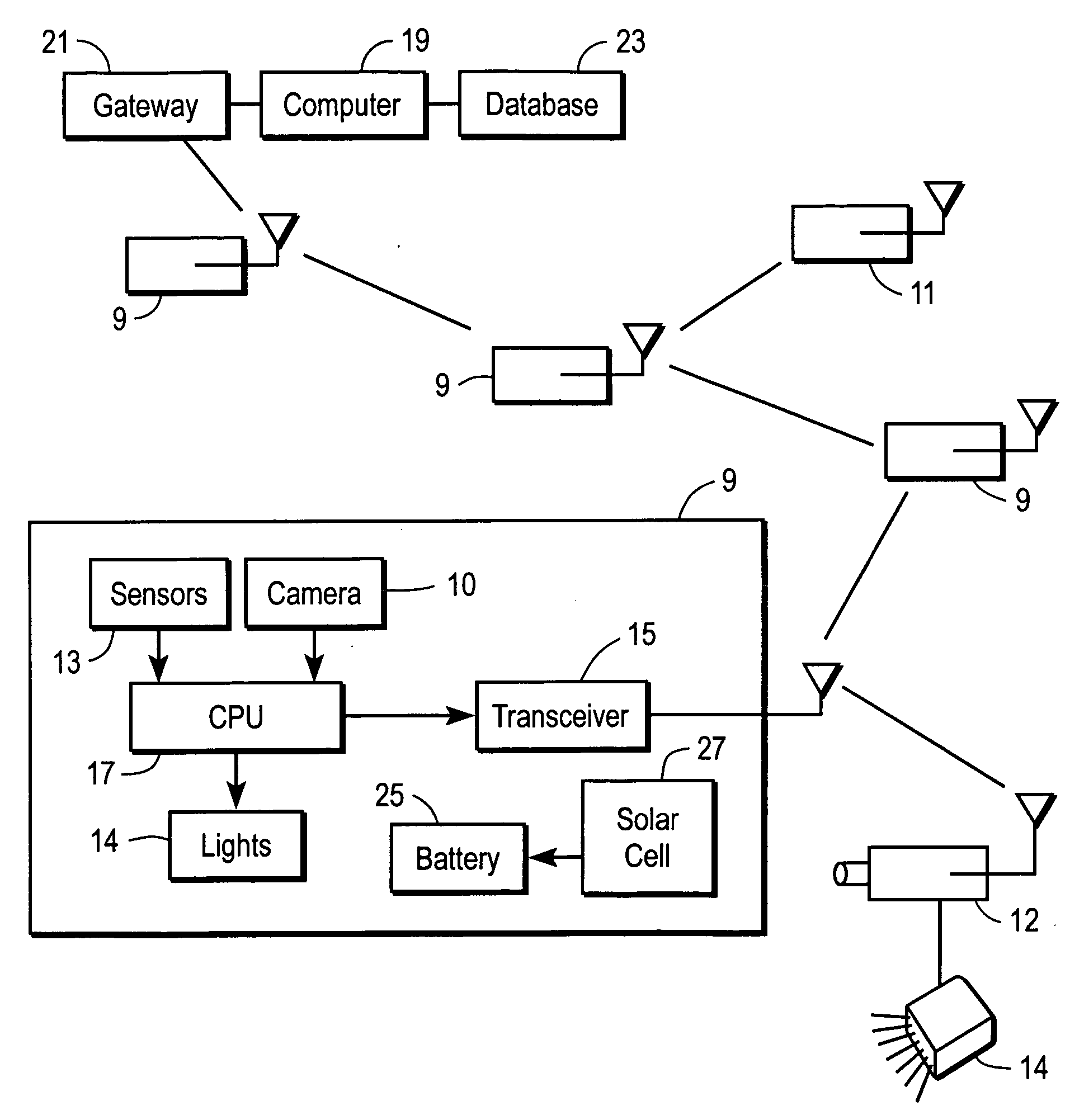
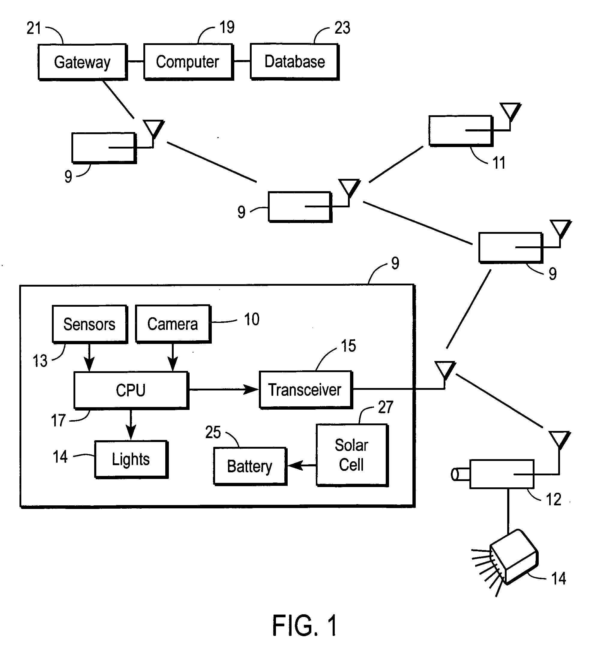
[0026] Referring now to FIG. 1, there is shown a plurality of individual sensor modules 9 deployed at spaced locations, for example, along a peripheral boundary of an area to be secured. Of course, additional sensor modules 11 may be deployed along pathways or entryways or other locations within the area to be secured in order to monitor traffic or other activities.

[0027] Each sensor module 9, 11 includes a proximity sensor 13 that may be, for example, a passive infrared sensor that responds to the presence or proximity of a warm object such as an individual, vehicle, or the like. Alternatively, the proximity sensor 13 may be an active infrared or radio or ultrasonic sensor that emits a signal and senses any echo attributable to presence of a reflective object within a sensing field of view. Of course, other sensors such as vibration detectors or light detectors may be used to respond to the presence of an intruding object.

[0028] In addition, each sensor module 9 includes a transc...


PUM


Abstract

A plurality of modules interact to form an adaptive network in which each module transmits and receives data signals indicative of proximity of objects. A central computer accumulates the data produced or received and relayed by each module for analyzing proximity responses to transmit through the adaptive network control signals to a selectively-addressed module to respond to computer analyses of the data accumulated from modules forming the adaptive network. Interactions of local processors in modules that sense an intrusion determine the location and path of movements of the intruding object and control cameras in the modules to retrieve video images of the intruding object. Multiple operational frequencies in adaptive networks permit expansions by additional networks that each operate at separate radio frequencies to avoid overlapping interaction. Additional modules may be introduced into operating networks without knowing the operating frequency at the time of introduction. Remote modules operating as leaf nodes of the adaptive network actively adapt to changed network conditions upon awaking from power-conserving sleep mode. New programs are distributed to all or selected modules under control of the base station.

Description

RELATED APPLICATION [0001] This application is a continuation-in-part of, and claims priority from, application Ser. No. 11 / 345,737 entitled “Interactive Surveillance-Network and Method,” filed on Feb. 1, 2006 by A. Broad et al, which is a continuation-in-part of application Ser. No. 11 / 152,350 entitled “Adaptive Surveillance Network and Method,” filed on Jun. 13, 2005 by A. Broad, which is a continuation-in-part of application Ser. No. 11 / 095,640 entitled “Surveillance System and Method,” filed on Mar. 30, 2005 by A. Broad et al, which applications are incorporated herein in the entirety by this reference to form a part hereof.FIELD OF THE INVENTION [0002] This invention relates to adaptive networks and more particularly to a self-adaptive network array of interactive modules that communicate information to local or central computers that issue commands for designated modules in the network. BACKGROUND OF THE INVENTION [0003] Typical surveillance systems that are used to secure bui...

Claims


Application Information

Patent Timeline
Patent Type & Authority Applications(United States)
IPC IPC(8): H04N7/18H04N9/47
CPCG08B25/009G08B25/10G08B29/188H04W52/0216H04W84/18Y02B60/50Y02D30/70
Inventor BROAD, ALANKAPUR, RAHULPRABHU, JAIDEVTURON, MARTIN ALBERTXU, NINGYANG, XINMILLER, MATT
Owner ACEINNA TRANSDUCER SYST CO LTD
Why Eureka
Try Eureka