Surface inspection apparatus

a technology of surface inspection and apparatus, which is applied in the field of surface inspection apparatus, can solve the problems of small gap, difficult to distinguish between, and inability to obtain desired engine performance, and achieve the effect of eliminating the effects of light scattering and accurate groove width determination

Inactive Publication Date: 2007-06-14
KIRIN TECH SYST CO LTD +1
View PDF5 Cites 27 Cited by
  • Summary
  • Abstract
  • Description
  • Claims
  • Application Information

AI Technical Summary

Benefits of technology

[0023] The two-dimensional image described above may be an image generated by a signal where the signal based on the amount of light received is processed by a Fourier transform, has the high-frequency components cut off and is further processed by an inverse Fourier transform. In addition, the two dimensional image described above may be an image generated by a signal where the signal based on the amount of light received is processed by a low-pass filter. Accordingly, it is possible to eliminate the effects of light scattering because of surface roughness and stain and the effects of other noise and carry out more accurate groove width determination.

Problems solved by technology

It is preferable for there to be absolutely no gap between the side surface of this concave part and the side surface of the valve seat, but a small gap actually arises because of manufacturing errors.
Furthermore, because the desired engine performance cannot be obtained if this gap becomes large, there is a need to measure the width of this gap accurately.
However, if the exposure spot is made small, it is easily affected by light scattering caused by surface roughness and stain, and the problem of its being difficult to distinguish between the grooves one wants to detect and this roughness and stain arises.
Therefore, it is difficult to use conventional surface inspection apparatuses for the detection of minute grooves.

Method used


Image

  • Surface inspection apparatus
  • Surface inspection apparatus
  • Surface inspection apparatus

Examples


Embodiment Construction

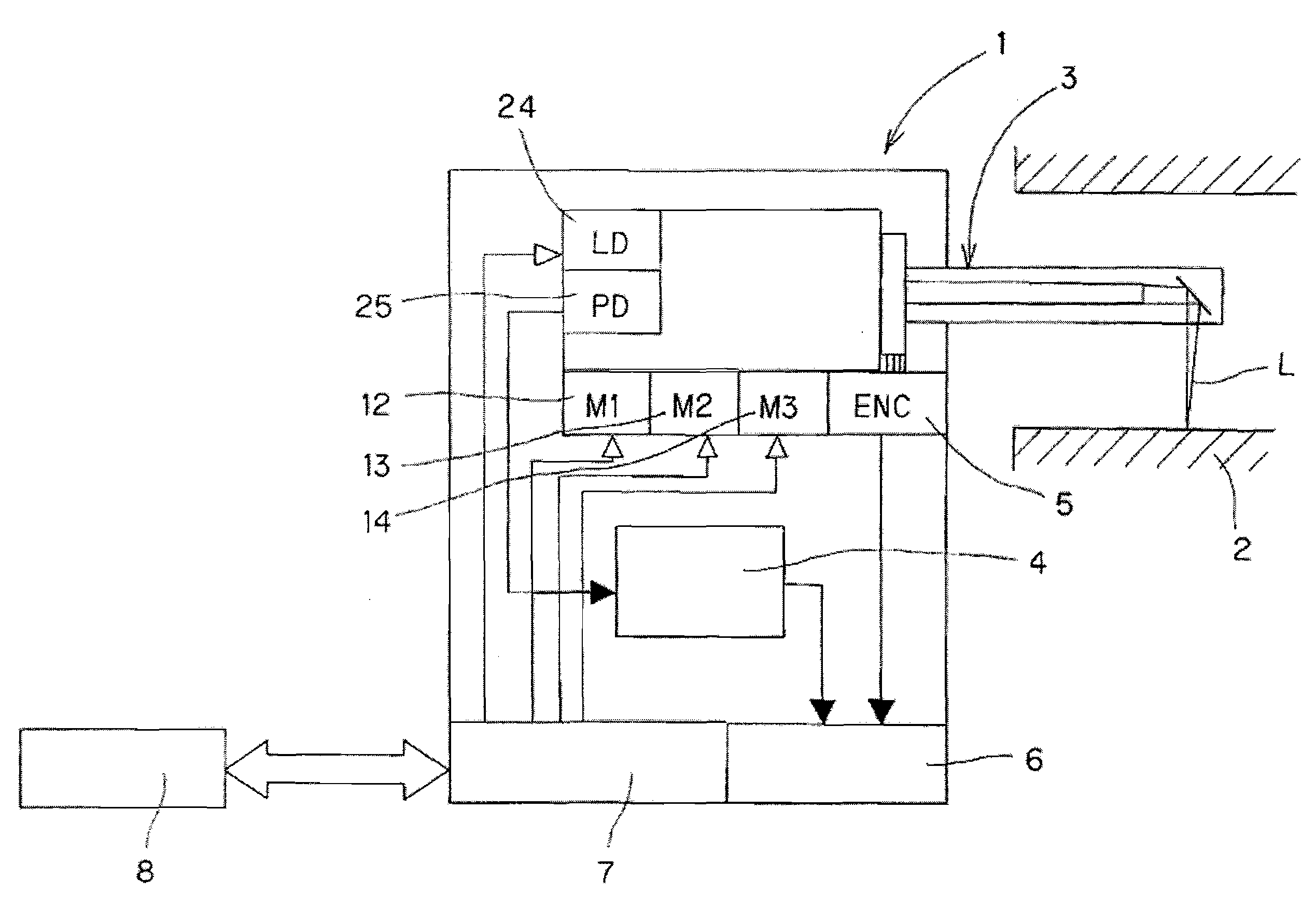
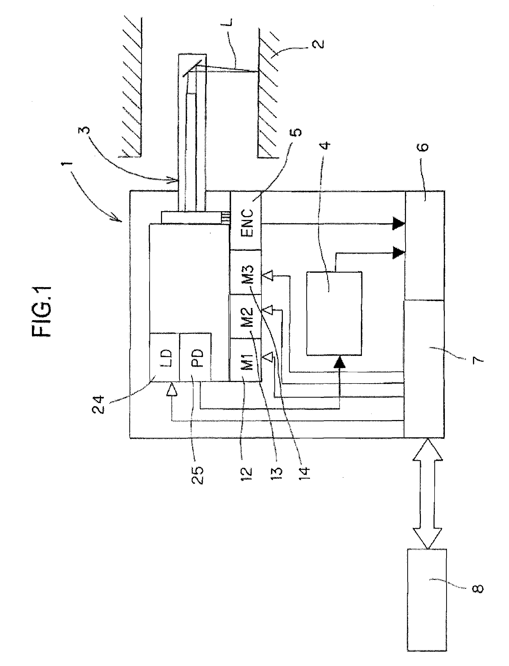
[0037]FIG. 1 is a schematic diagram of a surface inspection apparatus according to an embodiment of the present invention. As is shown in the drawing, a surface inspection apparatus 1 is inserted into a cylindrical body 2 and is provided with an inspection part 3 that receives the reflected light while projecting light L onto the inside surface of the cylindrical body 2, a non-linear amplifier 4, which is the nonlinear amplification means that amplifies the received light nonlinearly, an A / D converter 6, which is the A / D conversion means that performs an A / D conversion on a signal sent from the nonlinear amplifier part 4 using a sampling clock signal from an encoder 5, which is the clock signal generation means, a control part 7 that carries out various types of control on the inspection part 3 and the A / D converter 6, and a computation processing part 8 that carries out these various types of control and other processing that will be described later.

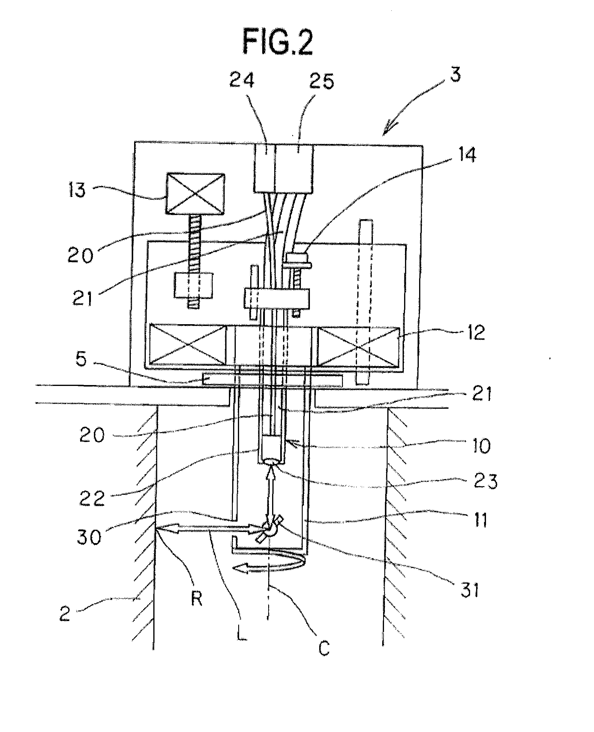
[0038]FIG. 2 is a drawing showi...


PUM

PropertyMeasurementUnit
angleaaaaaaaaaa
frequencyaaaaaaaaaa
surface inspectionaaaaaaaaaa

Abstract

In a surface inspection apparatus that receives, through receiving optical fibers, reflected light from light from a light source projected onto the surface of an article being inspected through a projection optical fiber and generates a two-dimensional image corresponding to the surface of that article being inspected based on the amount of that light received, a plurality of receiving optical fibers are disposed around the projection optical fiber and the diameter of those receiving optical fibers is greater than the diameter of the projection optical fiber.

Description

BACKGROUND OF THE INVENTION [0001] 1. Field of the Invention [0002] The present invention relates to a surface inspection apparatus for inspecting foreign matter, fine grooves or scratches present on the surface of an article being inspected and inspecting grooves present on the inside surface of a cylindrical body being inspected. [0003] 2. Background Art [0004] Typically, a concave part is formed on the inside surface of an automobile engine cylinder head, and a ring-shaped valve seat is installed in this concave part to assure the air tightness of the valves and durability. It is preferable for there to be absolutely no gap between the side surface of this concave part and the side surface of the valve seat, but a small gap actually arises because of manufacturing errors. Furthermore, because the desired engine performance cannot be obtained if this gap becomes large, there is a need to measure the width of this gap accurately. [0005] Surface inspection apparatuses that receive, ...

Claims


Application Information

Patent Timeline
Patent Type & Authority Applications(United States)
IPC IPC(8): G01N21/88
CPCG01N21/954G01N2021/4747G01N2021/9546G01N2201/08
Inventor FUKAMI, YUKIKOISHIKURA, TORUMORI, HIDEO
Owner KIRIN TECH SYST CO LTD
Why Eureka
Try Eureka