
Information storage medium, recording method, and recording apparatus

a technology of information storage and recording equipment, applied in the field of information storage equipment, can solve the problems of reducing the capacity of the data area, unable to reproduce sufficiently reliable information from the part on which information is recorded with an unadjusted recording waveform, and predetermined capacity of each area, so as to achieve high density, improve recording sensitivity, and high speed recording

Inactive Publication Date: 2007-06-14
MARUYAMA SUMITAKA +4
View PDF0 Cites 5 Cited by
  • Summary
  • Abstract
  • Description
  • Claims
  • Application Information

AI Technical Summary

Benefits of technology

[0099] 1) Relationship between track pitch / bit pitch and optimal recording power:
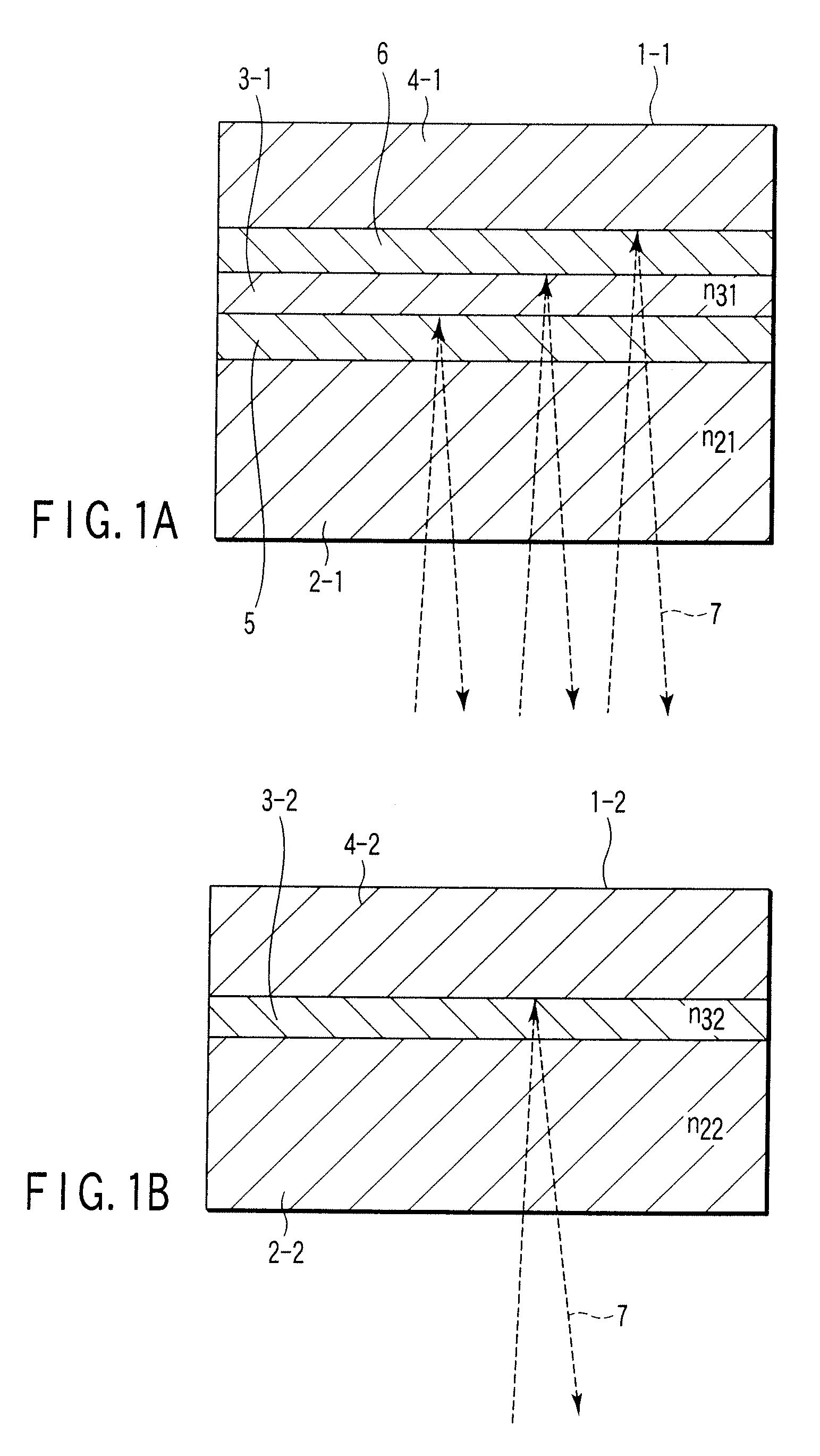
[0100] Conventionally, in the case of a principle of recording with a substrate shape change, if a track pitch is narrowed, a “cross-write” or a “cross-erase” occurs, and if bit pitches are narrowed, an inter-code crosstalk occurs. As in the present embodiment, since a principle of recording without a substrate shape change is devised, it becomes possible to achieve high density by narrowing track pitches / bit pitches. In addition, at the same time, in the above described principle of recording, recording sensitivity is improved, enabling high speed recording and multi-layering of a recording film because optimal recording power can be lowly set.
[0101] 2) In optical recording with a wavelength of 620 nm or less, an ECC block is composed of a combination of a plurality of small ECC blocks and each item of data ID information in two sectors is disposed in a small ECC block which is different from another:
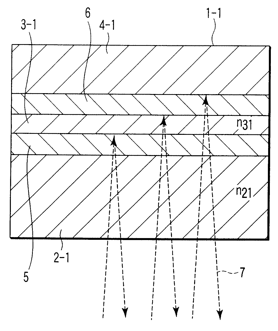
[0102] According to the invention, as shown in FIG. 1B, a local optical characteristic change in a recording layer 3-2 is a principle of recording, and thus, an arrival temperature in the recording layer 3-2 at the time of recording is lower than that in the conventional principle of recording due to plastic deformation of a transparent substrate 2-2 or due to thermal decomposition or gasification (evaporation) of an organic dye recording material. Therefore, a difference between an arrival temperature and a recording temperature in a recording layer 3-2 at the time of playback is small. In the present embodiment, an interleaving process between small ECC blocks and data ID allocation are contrived in one ECC block, thereby improving reproduction reliability in the case where a recording film is degraded at the time of repetitive playback.
[0103] 3) Recording is carried out by light having a wavelength which is shorter than 620 nm, and a recorded portion has a higher reflection factor than a non-recording portion:
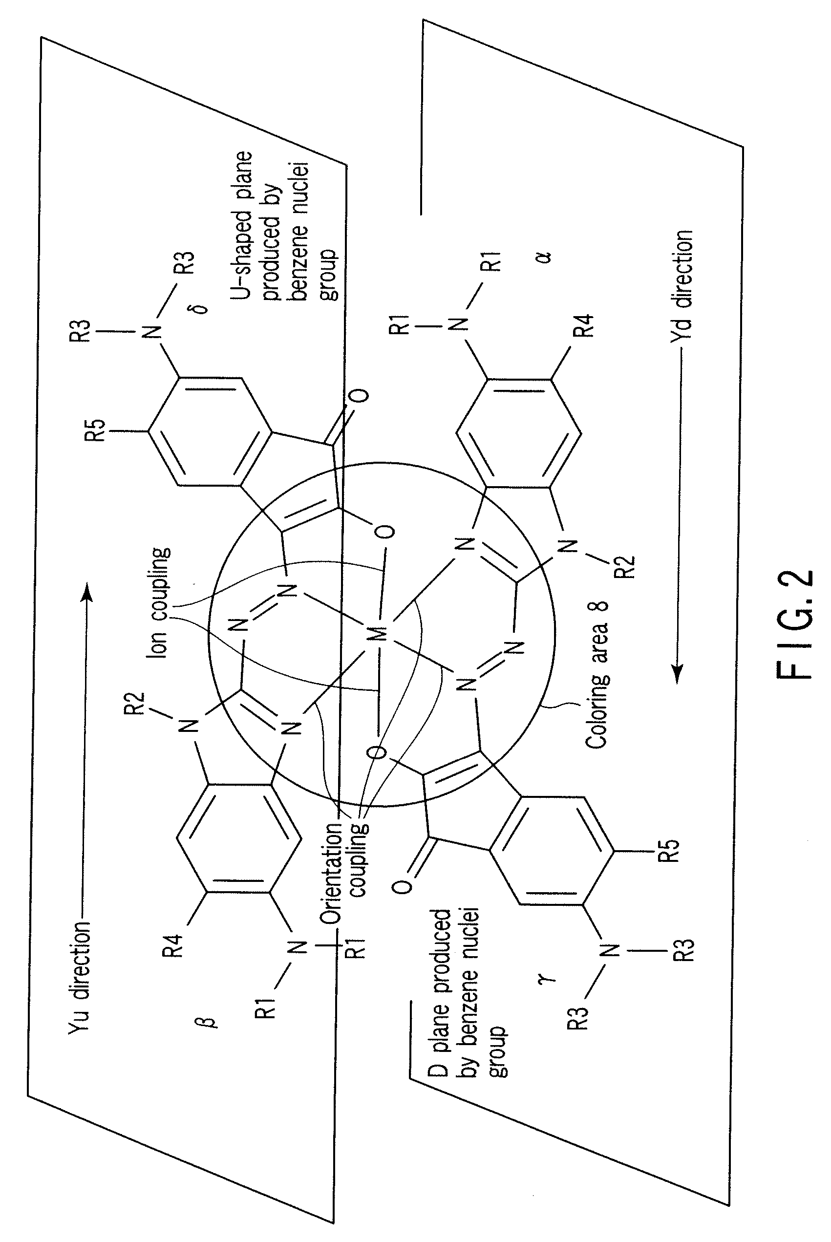
[0104] Under the influence of absorption spectrum characteristics of a general organic dye material, under the control of light having a wavelength which is shorter than 620 nm, the light absorbance is significantly lowered, and recording density is lowered. Therefore, a very large amount of exposure is required to generate a substrate deformation which is a principle of recording in a conventional DVD-R. By employing an “Low to High (hereinafter, abbreviated to as L-H) organic dye recording material” whose reflection factor is increased more significantly than that of an unrecorded portion in a portion (recording mark) recorded as in the present embodiment, a substrate deformation is eliminated by forming a recording mark using a “discoloring action due to dissociation of electron coupling”, and recording sensitivity is improved.

Problems solved by technology

The capacity of each area is predetermined and unchangeable.
Sufficiently reliable information cannot be reproduced from a part on which the information is recorded with an unadjusted recording waveform.
However, in this case, the capacity of the data area reduces.
As a result, even though the unrecorded areas in the RMA area and the PCA area sufficiently remain, the capacity of the data area may not be large enough.
The interlayer crosstalk causes a problem not only at the time of reproducing but also at the time of recording.

Method used


Image

  • Information storage medium, recording method, and recording apparatus
  • Information storage medium, recording method, and recording apparatus
  • Information storage medium, recording method, and recording apparatus

Examples


Embodiment Construction

[0096] Various embodiments according to the invention will be described hereinafter with reference to the accompanying drawings. In general, according to one embodiment of the invention, an information recording method which records information on an information storage medium in which layer 0 and layer 1 are sequentially arranged as recording layers from a read surface; a system lead-in area, a data lead-in area, a data area, and a middle area are sequentially arranged from an inner circumference of the layer 0; a system lead-out area, a data lead-out area, a data area, and a middle area are sequentially arranged from an inner circumference of the layer 1; a guard track zone is arranged on a side of the data area in the data lead-out area; and a reference code zone, an R physical format information zone, a recording position management zone, and a drive test zone are arranged in the data lead-in area of the layer 0 corresponding to the guard track zone, the method comprises padding...


PUM

PropertyMeasurementUnit
wavelengthaaaaaaaaaa

Abstract

A system lead-in area, data lead-in area, data area, and middle area are sequentially arranged from an inner circumference of layer 0. A system lead-out area, data lead-out area, data area, and middle area are sequentially arranged from an inner circumference of layer 1. A guard track zone is arranged in the data lead-out area. A reference code zone, R physical format information zone, recording position management zone, and drive test zone are arranged in the data lead-in area of the layer 0 corresponding to the guard track zone. Padding of the guard track zone of the data lead-out area is performed after padding of the drive test zone of data lead-in area and recording of the recording position management zone, the reference code zone of the data lead-in area, and the R physical format information zone of the data lead-in area.

Description

CROSS-REFERENCE TO RELATED APPLICATIONS [0001] This application is based upon and claims the benefit of priority from Japanese Patent Applications No. 2005-319684, filed Nov. 2, 2005; and No. 2006-097437, filed Mar. 31, 2006, the entire contents of both of which are incorporated herein by reference. BACKGROUND [0002] 1. Field [0003] The present invention relates to an information storage medium such as a recordable optical disc, a recording method, and a recording apparatus. [0004] 2. Description of the Related Art [0005] In recent years, a digital versatile disc (DVD) has been practically used as a large-capacity optical disc. As a recordable DVD, a recordable DVD-R, a rewritable DVD-RW, and a DVD-RAM have been standardized. Once information is recorded on a recordable disc DVD-R, a recorded area cannot be rewritten. A conventional recordable DVD-R includes a power calibration area (PCA), a recording management area (RMA), and a data recording area (DA) in which an actual recording...

Claims


Application Information

Patent Timeline
Patent Type & Authority Applications(United States)
IPC IPC(8): G11B7/20G11B3/74
CPCG11B7/00736G11B20/1217G11B27/322G11B2007/0013G11B2020/1229G11B2020/1231G11B2020/1278G11B2020/1288G11B2220/237G11B2220/2579G11B7/007G11B20/12
Inventor MARUYAMA, SUMITAKAANDO, HIDEOWATABE, KAZUOKASHIHARA, YUTAKAOGAWA, AKIHITO
Owner MARUYAMA SUMITAKA
Learn More