
Efficient simulation of dominantly linear circuits

a dominantly linear, efficient technology, applied in the direction of electric digital data processing, instruments, computing, etc., can solve the problems of large number of cells, difficult to simulate physical design without the aid of computers, and complex connections between cells, so as to speed up the simulation of dominantly linear circuits and efficiently simulates

Inactive Publication Date: 2007-06-14
MACHINES INT BUSINESS
View PDF11 Cites 10 Cited by
  • Summary
  • Abstract
  • Description
  • Claims
  • Application Information

AI Technical Summary

Benefits of technology

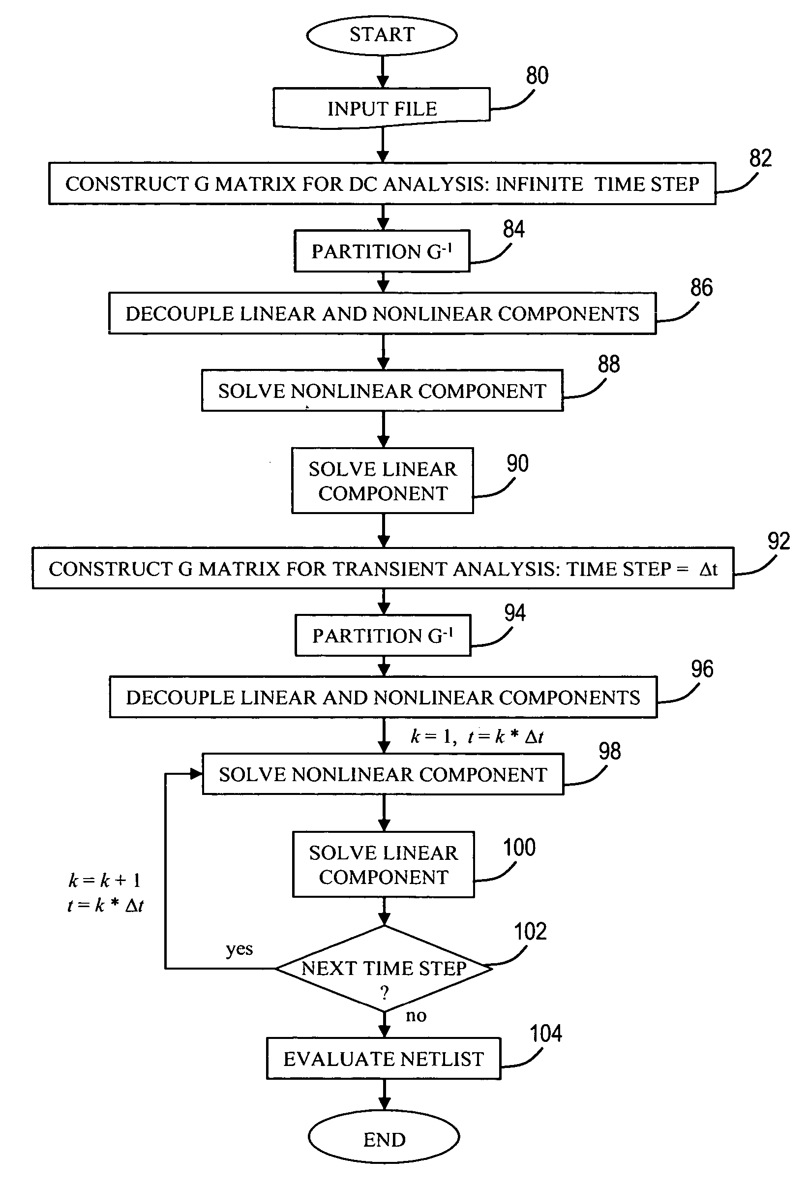
[0012] It is therefore one object of the present invention to provide an improved method of simulating circuit parameters such as voltage or current in an integrated circuit design.
[0013] It is another object of the present invention to provide such a method which efficiently simulates circuit parameters of a dominantly linear circuit having a relatively small number of nonlinear elements.
[0014] It is yet another object of the present invention to provide a scheme to speed up the simulation of dominantly linear circuits using transient analysis flow.

Problems solved by technology

An IC may include a very large number of cells and require complicated connections between the cells.
Due to the large number of components and the details required by the fabrication process for very large scale integrated (VLSI) devices, physical design is not practical without the aid of computers.
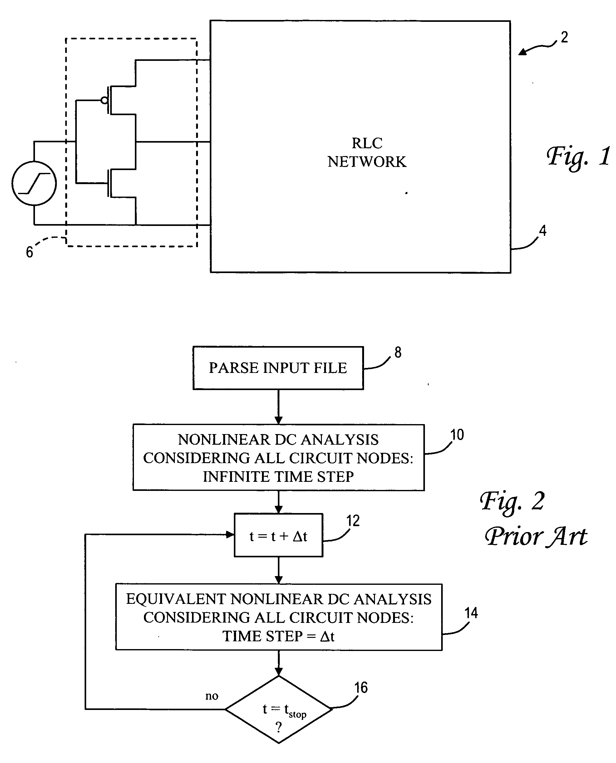
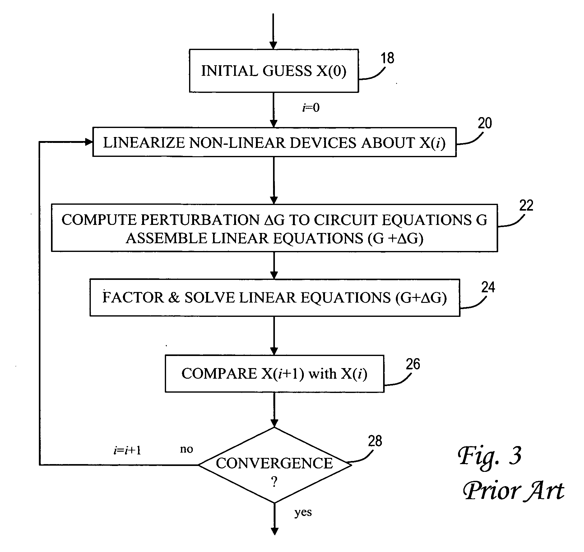
However, SPICE-like simulators are extremely inefficient in simulating large dominantly linear circuits that contain even a single nonlinear device since every Newton-Raphson iteration forms a new circuit matrix G. The Gaussian elimination of the MNA matrix uses triangular decomposition, also referred to as lower / upper (LU) factorization, followed by backward / forward substitution.
The per-iteration cost of transient simulation is dominated by LU factorization of the circuit matrix G, and can become overwhelming since a new large linear system has to be solved at each iteration.

Method used


Image

  • Efficient simulation of dominantly linear circuits
  • Efficient simulation of dominantly linear circuits
  • Efficient simulation of dominantly linear circuits

Examples


Embodiment Construction

)

[0027] The present invention provides a method for the efficient simulation of dominantly linear circuits using a reduced Newton-Raphson technique and reused factorization with a direct solver, as explained more fully below. A “dominantly linear circuit” refers to a circuit wherein the linear portions (e.g., resistive, capacitive and inductive elements) significantly outweigh the nonlinear portions (e.g., transistors or diodes). Although the present invention is applicable to circuits having a fairly large nonlinear portion, it is deemed most efficient when applied to a circuit in which the nonlinear portion is no more than about 1% of the circuit elements.

[0028] With reference now to the figures, and in particular with reference to FIG. 4, there is depicted one embodiment 30 of a computer system programmed to carry out the simulation of a dominantly linear circuit in accordance with one implementation of the present invention. System 30 includes a central processing unit (CPU) 32...


PUM


Abstract

A method of simulating a circuit parameter such as voltage or current for a dominantly linear circuit by constructing a circuit equation matrix whose elements correspond to nodes of the circuit, decoupling linear and nonlinear contributions to the circuit parameter based on a partition of an inverse matrix of the circuit equation matrix, computing linear and nonlinear components using the decoupled contributions, and combining the nonlinear and linear components to yield a state of the circuit parameter for a given time step. The computation of the nonlinear component includes Newton-Raphson iterations to linearize nonlinear devices of the circuit, wherein the Newton-Raphson technique is applied to the right-hand side of the circuit state matrix equation. The computations are iteratively repeated for successive time steps which are advantageously separated by a constant time interval to avoid further recalculation of the state matrix.

Description

BACKGROUND OF THE INVENTION [0001] 1. Field of the Invention [0002] The present invention generally relates to the fabrication and design of semiconductor chips and integrated circuits, and more particularly to a method of simulating a circuit parameter such as voltage or current for a circuit having linear components and nonlinear components. [0003] 2. Description of the Related Art [0004] Integrated circuits are used for a wide variety of electronic applications, from simple devices such as wristwatches, to the most complex computer systems. A microelectronic integrated circuit (IC) chip can generally be thought of as a collection of logic cells with electrical interconnections between the cells, formed on a semiconductor substrate (e.g., silicon). An IC may include a very large number of cells and require complicated connections between the cells. A cell is a group of one or more circuit elements such as transistors, capacitors, resistors, inductors, and other basic circuit eleme...

Claims


Application Information

Patent Timeline
Patent Type & Authority Applications(United States)
IPC IPC(8): G06F17/50
CPCG06F17/5036G06F30/367
Inventor BEATTIE, MICHAEL W.KRAUTER, BYRON L.ZHENG, HUI
Owner MACHINES INT BUSINESS
Learn More