Positioning device

a positioning device and positioning technology, applied in the direction of instruments, manufacturing tools, arms, etc., can solve the problems of affecting the performance behavior of the positioning device, the interference of the cable in a very short time with the operation behavior, etc., and achieve the effect of improving the positioning accuracy

Inactive Publication Date: 2007-06-21
DR JOHANNES HEIDENHAIN GMBH
View PDF10 Cites 9 Cited by
  • Summary
  • Abstract
  • Description
  • Claims
  • Application Information

AI Technical Summary

Benefits of technology

[0005]Example embodiments of the present invention provide a positioning device which makes possible an improvement of the positioning accuracy compared to conventional uni

Problems solved by technology

Such a cable may interfere in a very short time with the operational behavior, especially with the exact positioning of the swivel arm of the STW.
This is

Method used


Image

  • Positioning device
  • Positioning device
  • Positioning device

Examples


Embodiment Construction

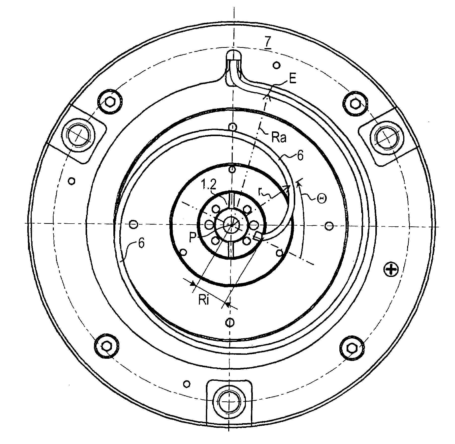
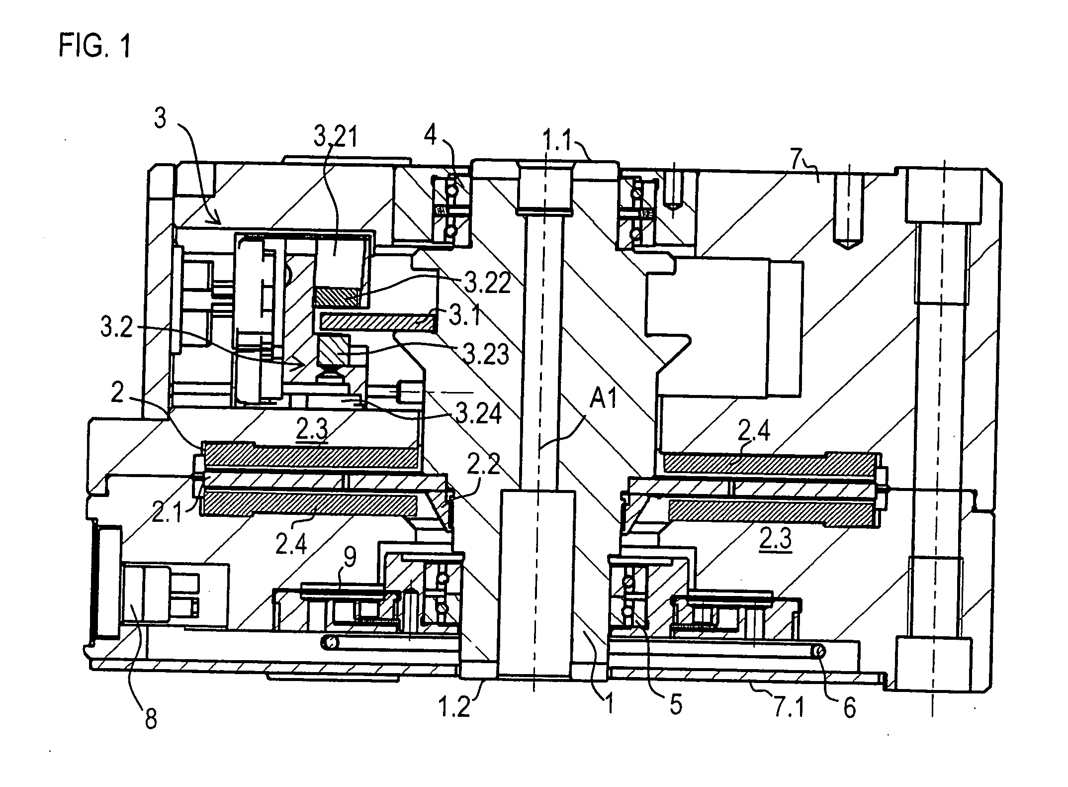
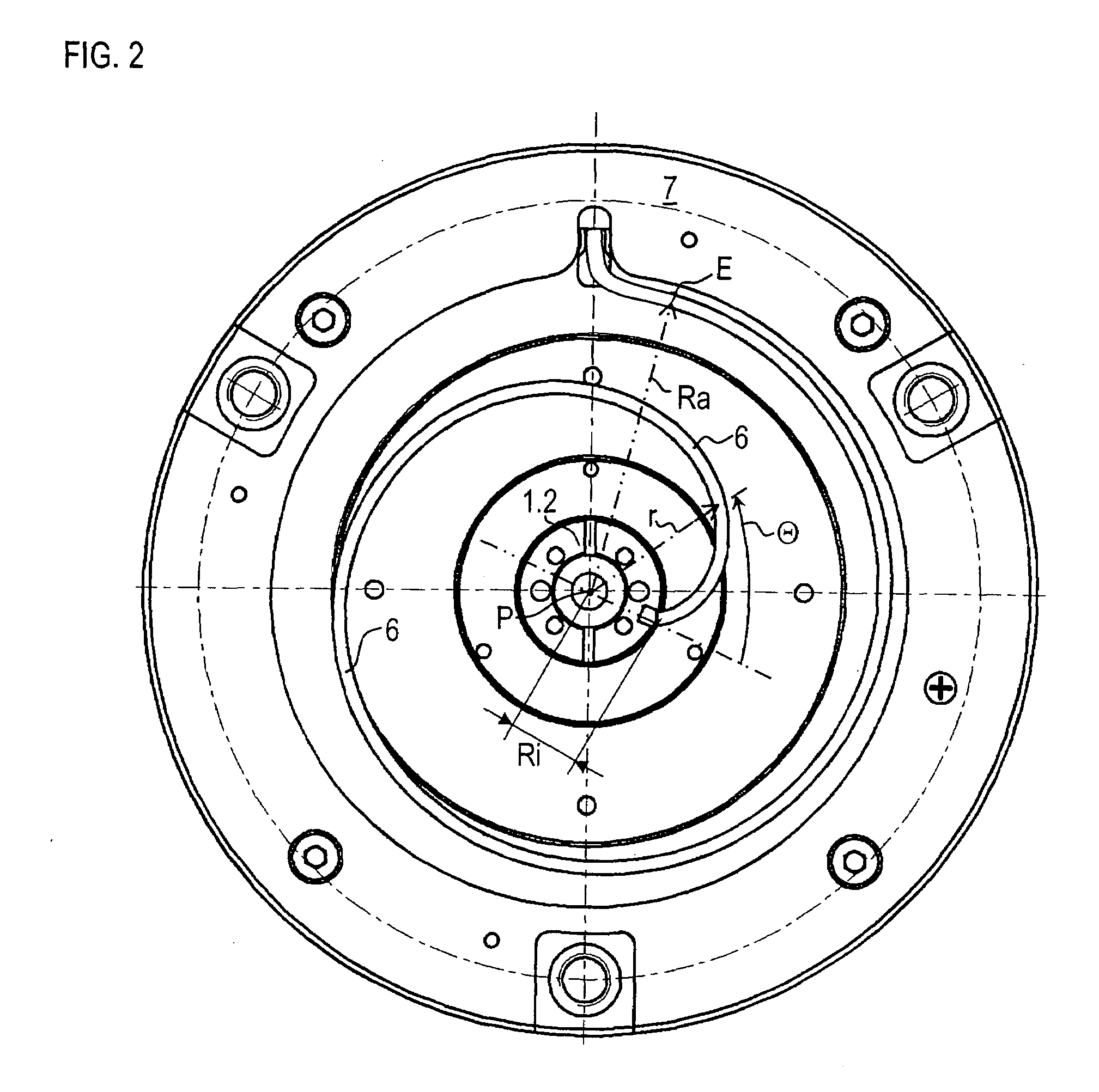
[0030]FIG. 1 illustrates a positioning device as it is used in connection with STW. As illustrated in FIG. 1, a shaft 1 is able to swivel about an axis A1 and has a shaft end 1.1, to which a swivel arm for writing to a hard disk may be attached. As illustrated, housing 7 is arranged as a substantially cylindrical component. According to this, housing 7 has a lateral side which limits the positioning device spatially in a radial manner. In addition, two end faces of the housing border the positioning device in its axial extension. At the lower end face, a detachable housing cover 7.1 is arranged. An electrical coupling 8, e.g., a socket for accommodating a plug connector, is arranged counter to this at the lateral side of housing 7.

[0031]Within housing 7, at shaft 1, there are two roller bearing units 4, 5, which each include two ball bearings 4.1, 4.2, 5.1, 5.2. Roller bearing unit 5 is mounted such that it serves as a fixed bearing, e.g., it is arranged as an axially rigid support ...


PUM


Abstract

A positioning device includes a housing and a shaft that is able to be swiveled about a centrical position relative to the housing, at whose one end an element that is to be positioned is attachable. Furthermore, the positioning device has a swivel drive and a position measuring device. A cable, for the electrical connection of swivelable parts in the positioning device to a stationary unit, has a spiral-shaped course leading radially outwardly, starting from the shaft that is located in the centrical position.

Description

CROSS-REFERENCE TO RELATED APPLICATIONS[0001]This application claims priority to Application No. 10 2005 057 865.9, filed in the Federal Republic of Germany on Dec. 2, 2005, which is expressly incorporated herein in its entirety by reference thereto.FIELD OF THE INVENTION[0002]The present invention relates to a positioning device, which may be suitable, e.g., for the precise movement of a swivel arm for a servo track writer.BACKGROUND INFORMATION[0003]Positioning devices of this type are often used in servo track writers (STW), where the tracks for magnetizable hard disks are formatted or written. For this purpose, a positioning device in the STW swivels a shaft, to which a swivel arm is attached. At its end, a write head is provided which is ultimately moved by the swivel motion of the shaft and is positioned in a highly precise manner, so that as many tracks as possible per unit surface area of the hard disk can be configured. The number of tracks formatted per surface area unit o...

Claims


Application Information

Patent Timeline
IPC IPC(8): B25J17/02
CPCH02K5/225Y10T74/20323H02K33/00
Inventor HOEFER, VOLKERSCHEGLMANN, GERHARD
Owner DR JOHANNES HEIDENHAIN GMBH
Why Eureka
Try Eureka