Curved window roller blind for motor vehicles

Inactive Publication Date: 2007-06-21
BOS
View PDF13 Cites 9 Cited by
  • Summary
  • Abstract
  • Description
  • Claims
  • Application Information

AI Technical Summary

Benefits of technology

[0007] The actual roller blind shaft, which comprises a combination of several tubular shaft segments, sits on the rigid axle. The inner diameter of the roller blind shaft is significantly greater than the outer diameter of the rigid axle. Bearing elements are arranged between the axle and the roller blind shaft. The bearing elements support the shaft segments on the axle. The individual shaft segments can rotate without jamming even for a large curvature. The individual shaft segments do not have excessive play, which improves the precision of the support and prevents rattling noises. Due to the bearing elements, the point at which the support is realized relative to the corresponding shaft segment can be predetermined exactly. It is advantageous if the bearing elements lie as much as possible next to the front ends of the shaft segments, so that a slight projection can be prevented.
[0009] Advantageously, the rigid shaft acting as a carrier device can comprise a tube. The tube has the advantage of being very resistant to bending and being relatively light weight. In addition, additional parts of the window roller blind can be housed in the tube if necessary.
[0013] The projections can be formed in one piece, for example, with corresponding beads being formed in the case of the use of metal pipes. However, if the shaft segments are made from plastic tube sections, the projections can also be formed in one piece. In each case, the height of the projections is such that the relevant shaft segment can rotate on the axle without jamming.
[0016] To prevent the roller blind from crumpling, the roller blind can be elastically extendable in the transverse direction.

Problems solved by technology

This can be a problem not merely for aesthetic reasons.
First and foremost are the spatial conditions in the molded area of the vehicle, which can present problems under these circumstances.
The window roller blind must be arranged at a significant distance from the rear window, which significantly reduces head room for the rear passengers.
This is a considerable problem particularly with smaller vehicles, in which there is already a notorious lack of room.
Only curving the extension rod to which the roller blind is fixed in the upper area is typically not sufficient to improve the head room.
In addition, curving the rod in the upper area would be particularly difficult.
With such an arrangement, if a straight winding shaft is used, the roller blind would constantly graze the edge of the slot, which is viewed as unfavorable.
In this known arrangement, the corrugated tube consists of plastic, so that there is a risk that the corrugated tube will become significantly torqued relative to the length of the rear window roller blind, for example.
The force which must be developed by the spring motor to completely extend the roller blind can be substantial, because otherwise the roller blind may oscillate too much due to vehicle vibrations.

Method used


Image

  • Curved window roller blind for motor vehicles
  • Curved window roller blind for motor vehicles
  • Curved window roller blind for motor vehicles

Examples


Embodiment Construction

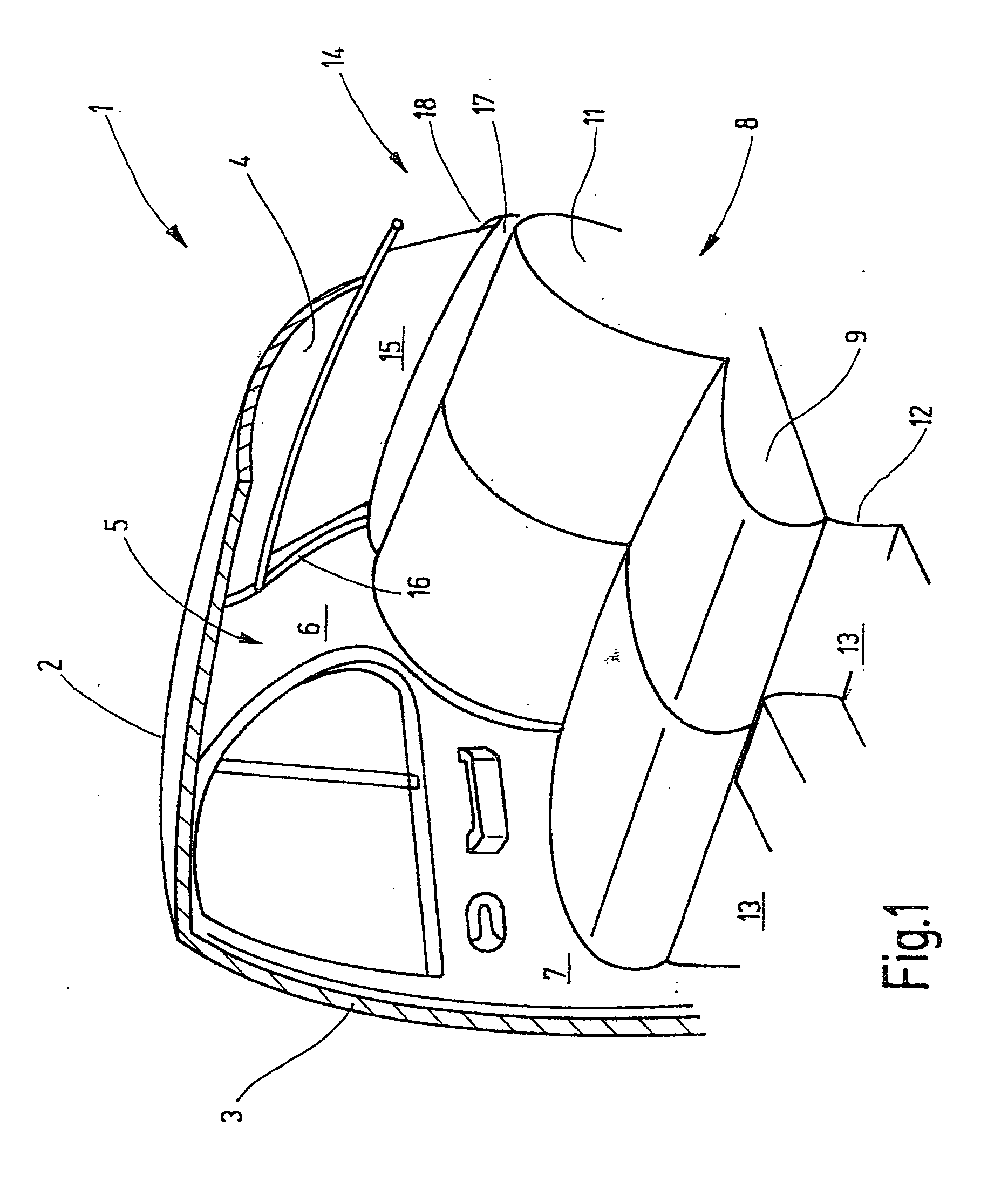
[0028] The rear interior area of an exemplary passenger vehicle is shown in FIG. 1. The not shown side of the rear interior area of the vehicle is the mirror image of the illustrated side. The illustration is simplified in that, for example, car body inner structures, such as braces and attachment elements are not shown because their representation is not necessary for understanding the invention.

[0029] The illustrated car body section 1 has a roof 2 from the side of which a B-column 3 leads downwards to a floor assembly. A corresponding B-column can be provided on the opposing side of the vehicle. The roof 2 transitions at its rear edge into a rear window 4. The rear window 4 ends at the side at a C-column 5, which is located at a distance to the B-column 3. The C-column 5 carries an inner lining 6. A rear right side door 7 is hinged to the B-column 3 in a known way between the B-column 3 and the C-column 5. A rear seat bench 8 is arranged at the height of the rear right side door...


PUM


Abstract

A rear window roller blind for motor vehicles has a curved extension profile and a curved winding shaft, which corresponds in its profile to the curvature of the extension profile. The winding shaft is composed of several winding shaft beads and is supported on an axle so that it can rotate. The course of the axle follows the curvature of the segmented winding shaft. A spring motor is arranged either within the axle or laterally next to the axle.

Description

BACKGROUND OF THE INVENTION [0001] In order to correspond to the shape of the body of a motor vehicle, the rear window of a motor vehicle is more or less cambered. The greater the camber of the rear window, the greater the distance in the center area between the inside of the rear window and a window roller blind, which travels along a plane. This can be a problem not merely for aesthetic reasons. First and foremost are the spatial conditions in the molded area of the vehicle, which can present problems under these circumstances. The window roller blind must be arranged at a significant distance from the rear window, which significantly reduces head room for the rear passengers. This is a considerable problem particularly with smaller vehicles, in which there is already a notorious lack of room. [0002] Only curving the extension rod to which the roller blind is fixed in the upper area is typically not sufficient to improve the head room. In addition, curving the rod in the upper are...

Claims


Application Information

Patent Timeline
IPC IPC(8): B60J1/20
CPCB60J1/2027B60J1/2033B60J1/205B60J1/208B60J1/2019B60J3/002B60J7/0015B60Y2200/11
Inventor HANSEN, MELFWALTER, HERBERTMAIER, MATTHIAS
Owner BOS
Why Eureka
Try Eureka