
Belleville spring guide system

a spring guide and belleville technology, applied in the direction of ring springs, low internal friction springs, mechanical equipment, etc., can solve the problems of reducing the compressive force of the spring, stacked arrays of parallel discs, and hysteria of the load-deflection diagram, so as to reduce the lateral force, reduce the friction of operation, and limit the deflection of the belleville spring.

Active Publication Date: 2007-06-21
HALLIBURTON ENERGY SERVICES INC
View PDF16 Cites 43 Cited by
  • Summary
  • Abstract
  • Description
  • Claims
  • Application Information

AI Technical Summary

Benefits of technology

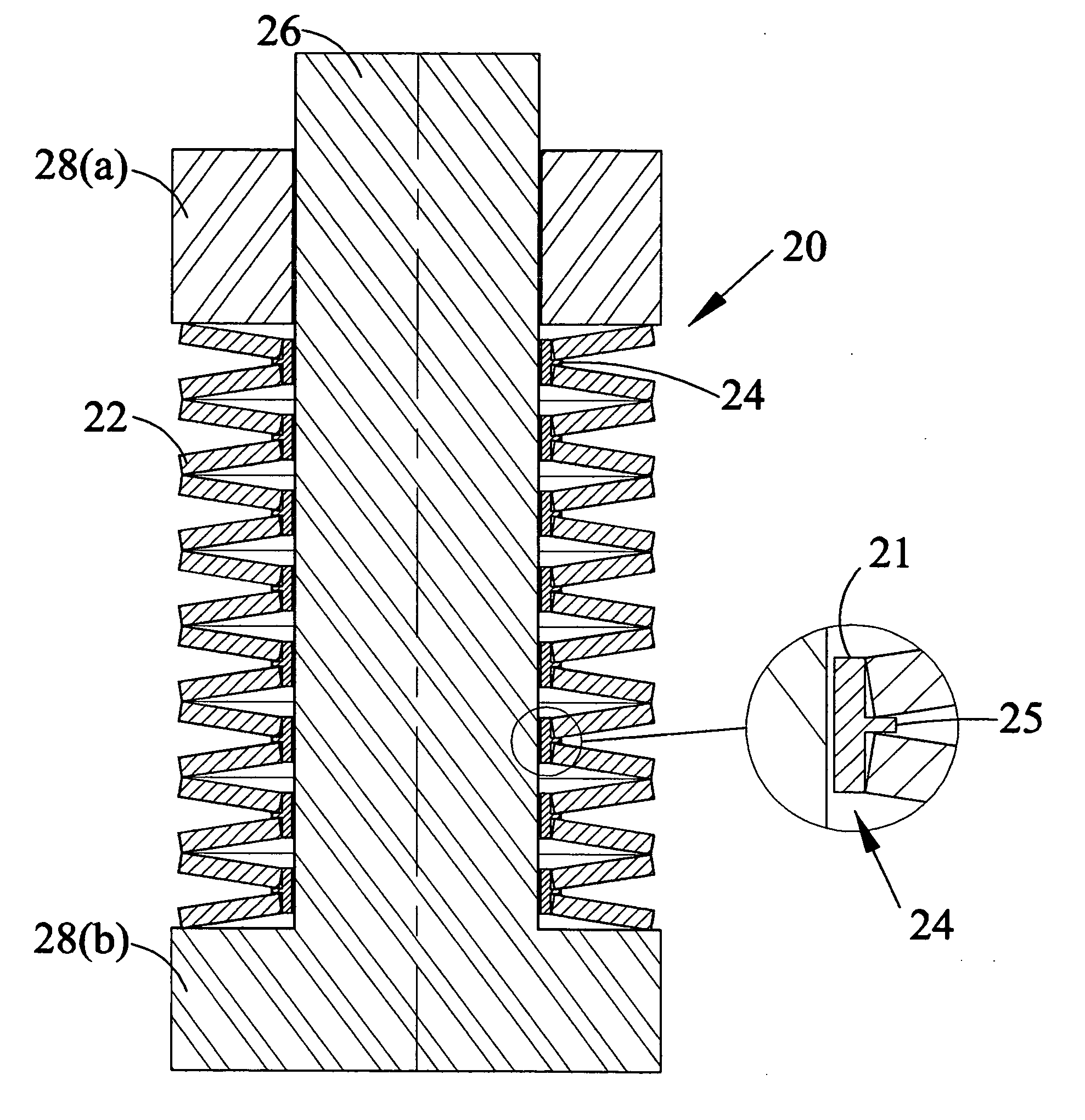
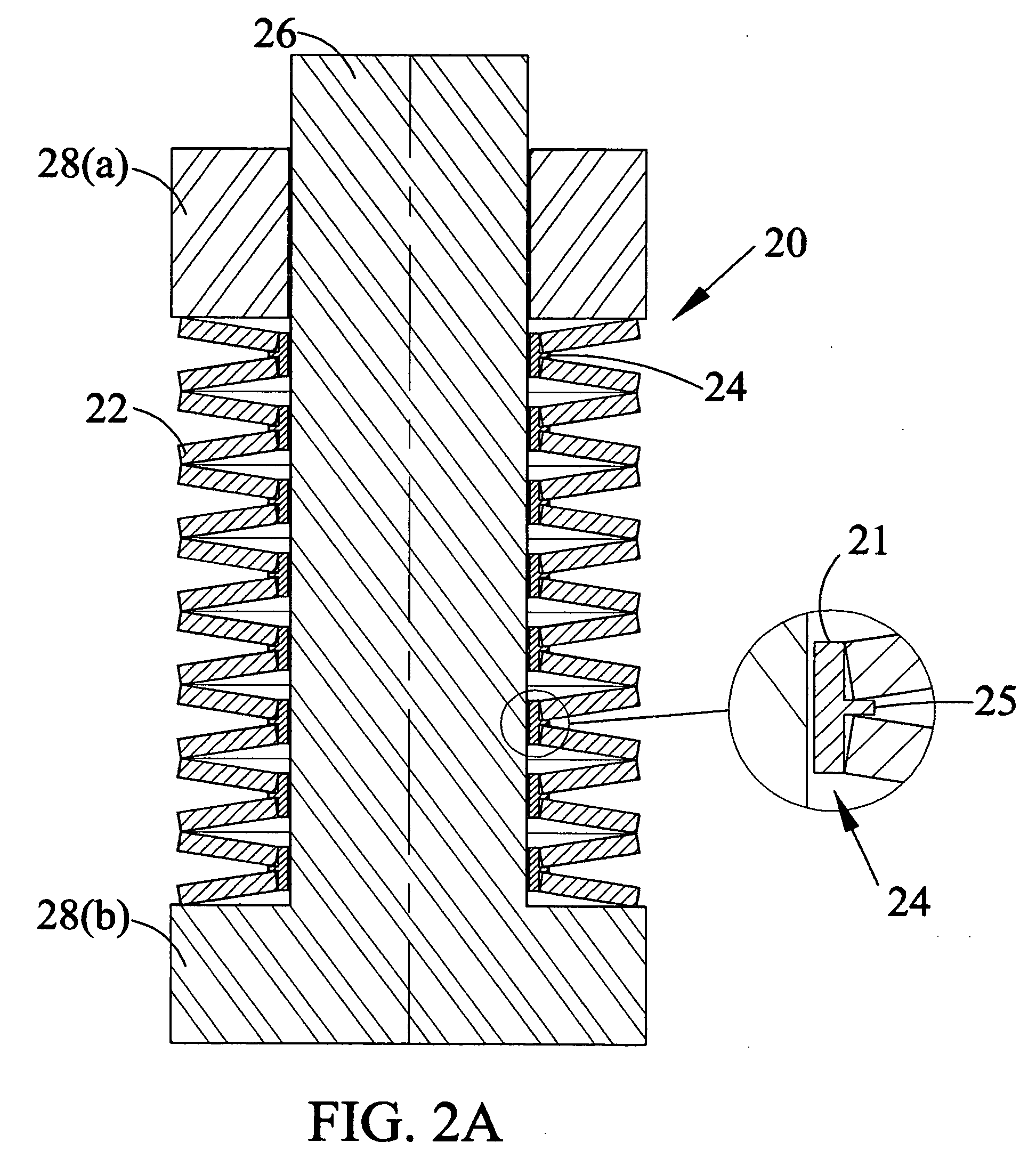
[0016] Apparatus is provided for reducing friction during operation of a stack of Belleville springs. The apparatus reduces lateral force on the springs in a stack (two or more springs) by providing a plurality of slidably coupled spring carriers between the springs and their guide mechanism. Apparatus is also provided for limiting deflection of Belleville springs. In other embodiments, no guide is provided and initial overlapping of spring carriers acts as a guide.

Problems solved by technology

This friction results in a variation between the calculated characteristic load curve and an actual load curve.
The force required to compress the springs is greater than the force recovered when the springs are relaxed, which means that a load-deflection diagram exhibits hysteresis.
The patent states that stacked arrays of parallel discs in abutting relationship produce undesirable hysteresis losses as a consequence of friction imposed by contacting surfaces through flexure of the washers and associated parts.
The patent also describes the limitations of Belleville springs because of frictional effects, explaining that the motion required to convert fluid pressure to mechanical work results in Belleville springs bending, sliding, scraping and plowing at the inside diameter or outside diameter of the springs.
The result of friction increases hysteresis and causes an increase in a switch's “deadband” (the difference between the point of operation and the point that it returns to its pre-operated state).
However, deviations in geometry of individual disc springs result in an uneven transmission of load from one spring to the next in a stack.
This results in forces tending to cause a lateral displacement of the springs, or a buckling of the stack, causing the springs to be pressed with force against the guide element.
For example, if the spring is deflected beyond a certain limit, it may reverse direction, or excess deflection may cause permanent change in spring characteristics.

Method used


Image

  • Belleville spring guide system
  • Belleville spring guide system
  • Belleville spring guide system

Examples


Embodiment Construction

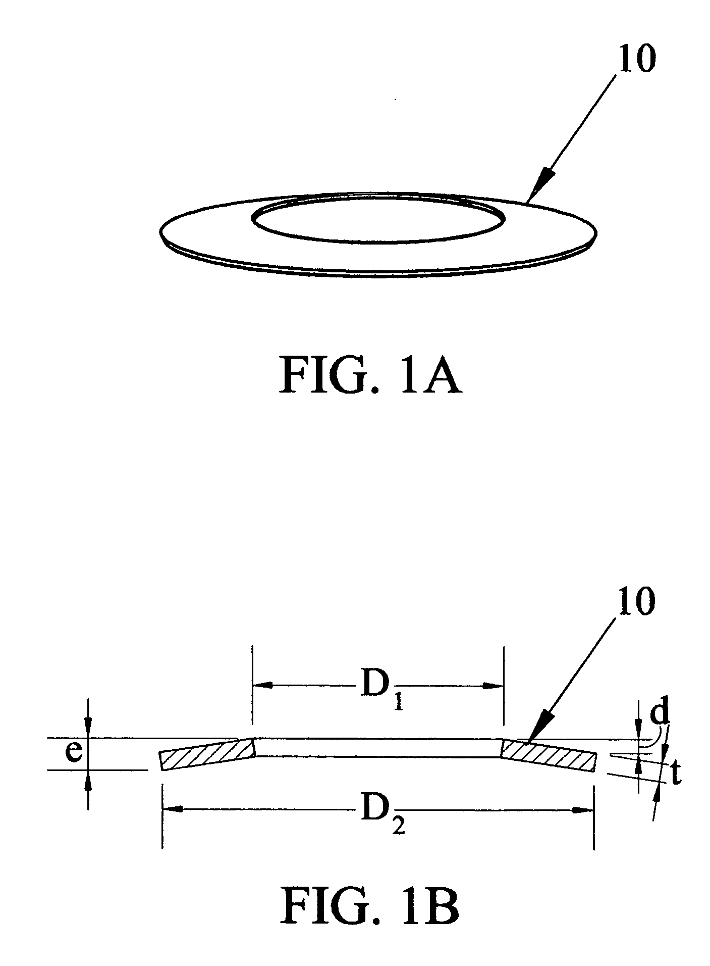
[0024]FIG. 1A shows a perspective view of a Belleville Washer. The washers are manufactured using materials, such as alloy steels, to meet specific material requirements. They should exhibit good fatigue life and minimum relaxation. A high alloy content material is commonly used as the spring steel. FIG. 1B identifies dimensions of Belleville Springs commonly used. Spring 10 is shown in FIG. 1A and FIG. 1B. D1 is the diameter of the opening, D2 is the external diameter of the spring, t is the thickness of the spring material, d is the maximum deflection of the spring when it is compressed, and e is the overall thickness of the spring in the uncompressed state. d=e−t. The spring may contain special properties for corrosion or other properties and may be coated with a number of different materials such as phosphate, galvanizing, mechanical zinc plating and electroless nickel plating. It may also be coated with the coating to minimize friction, which is discussed further below.

[0025] ...


PUM


Abstract

Apparatus and method are provided for decreasing frictional effects in stacks of Belleville springs and limiting deflection of the springs. In one embodiment, carriers for springs overlap and minimize the effects of lateral forces that are developed as springs in a stack are loaded. Carriers may be used on mandrel guides, in cylindrical guides or without a guide. In other embodiments, maximum load and defection of springs may be provided by the spring carriers.

Description

BACKGROUND OF THE INVENTION [0001] 1. Field of the Invention [0002] The present invention relates generally to Belleville or disc springs. More particularly, apparatus and method are provided for decreasing friction and hysteresis effects in operation of the springs. [0003] 2. Background of the Invention [0004] Belleville Springs are conical shaped circular springs that were patented in 1867 by Julian Belleville. They are also called “Belleville Washers,” because in plan view they have the shape of a washer. They are also called “disk springs.” Subsequent improvements have advanced this simple spring device to a sophisticated energy storage system that is used in many mechanical systems today. The springs are designed to be loaded in the direction perpendicular to the washer, i.e., by compressing the cone, and they may be loaded statically or dynamically. Disk springs are used, for example, in brakes, clutches, valves, shock absorbers, actuators, loading of flange joints, and in a v...

Claims


Application Information

Patent Timeline
IPC IPC(8): F16F1/34
CPCF16F1/32F16F3/02F16F2230/0052
Inventor EVANS, ROBERT W.
Owner HALLIBURTON ENERGY SERVICES INC
Learn More