
Method of Braking a Vehicle

a technology of braking and vehicle, applied in the direction of brake action initiation, braking system, position/direction control, etc., can solve the problems of vehicle instability, wheel lock-up, etc., and achieve the effect of accurate determination

Active Publication Date: 2007-06-21
JCB LANDPOWER
View PDF21 Cites 6 Cited by
  • Summary
  • Abstract
  • Description
  • Claims
  • Application Information

AI Technical Summary

Benefits of technology

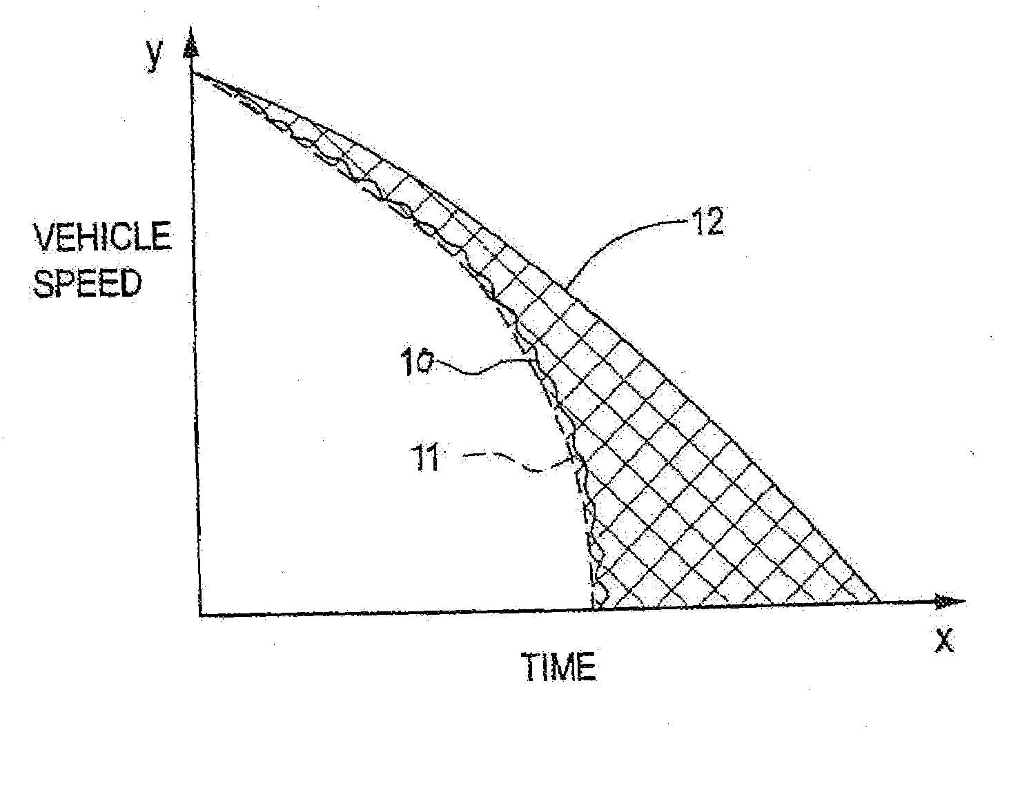
[0014]By virtue of the present invention, the inertia of the wheel, which may otherwise prevent the wheel being accelerated to bring its angular velocity close to the vehicle speed relative to the ground during periods in which the braking force is released by the ABS, is compensated for by the application of torque at least during those periods. Thus the risk of the ABS incorrectly determining the vehicle speed relative to the ground from its monitorings of wheel speed, is minimised, as the wheel will be accelerated by the applied torque to bring its angular velocity closer to the actual vehicle speed, and so the ABS will operate more effectively.
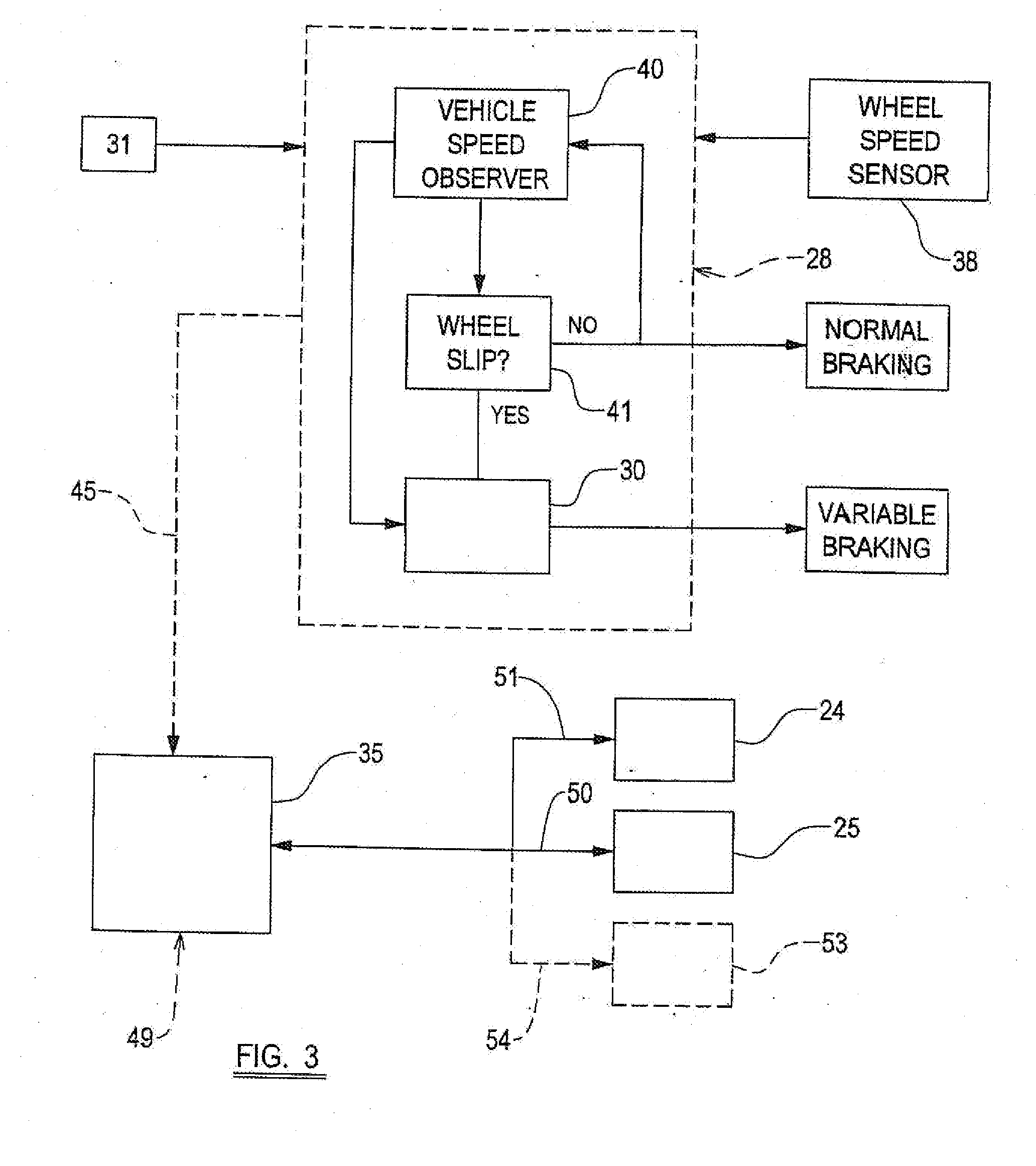
[0017]Thus the method may include providing a signal to an engine controller during braking, at least when the ABS is operated and it is desired to provide torque to the wheel, to maintain the engine speed at a minimum speed. This may involve not only preventing the engine speed falling below the minimum speed, but accelerating the engine speed if necessary up to a minimum speed if required.
[0020]It will be appreciated that in a typical arrangement, when an operator driving a vehicle with a CVT in automatic mode, removes his foot from a foot operated control pedal, as the engine speed reduces in response, the CVT will reduce the transmission ratio between the engine and the wheels.
[0028]Such an error may be determined by a torque controller which may analyse the actual wheel speed sensed, and compares it to a reference signal provided by the ABS which is indicative of vehicle deceleration determined by the ABS. If desired, there may be an auxiliary sensor such as an accelerometer to provide an input to the torque controller indicative of vehicle speed relative to the ground, independent of any wheel speed sensor, thus to enable the torque controller more accurately to determine any error between the vehicle speed determined by the ABS and actual vehicle speed relative to the ground.

Problems solved by technology

In the event that the engine speed decreases rapidly, by for example a driver taking his foot off the accelerator pedal, particularly where the road speed is large and the coefficient of friction between the road and the wheel is low, there is a risk that the wheels will be locked up by the transmission, possibly leading to vehicle instability.

Method used


Image

  • Method of Braking a Vehicle
  • Method of Braking a Vehicle
  • Method of Braking a Vehicle

Examples


Embodiment Construction

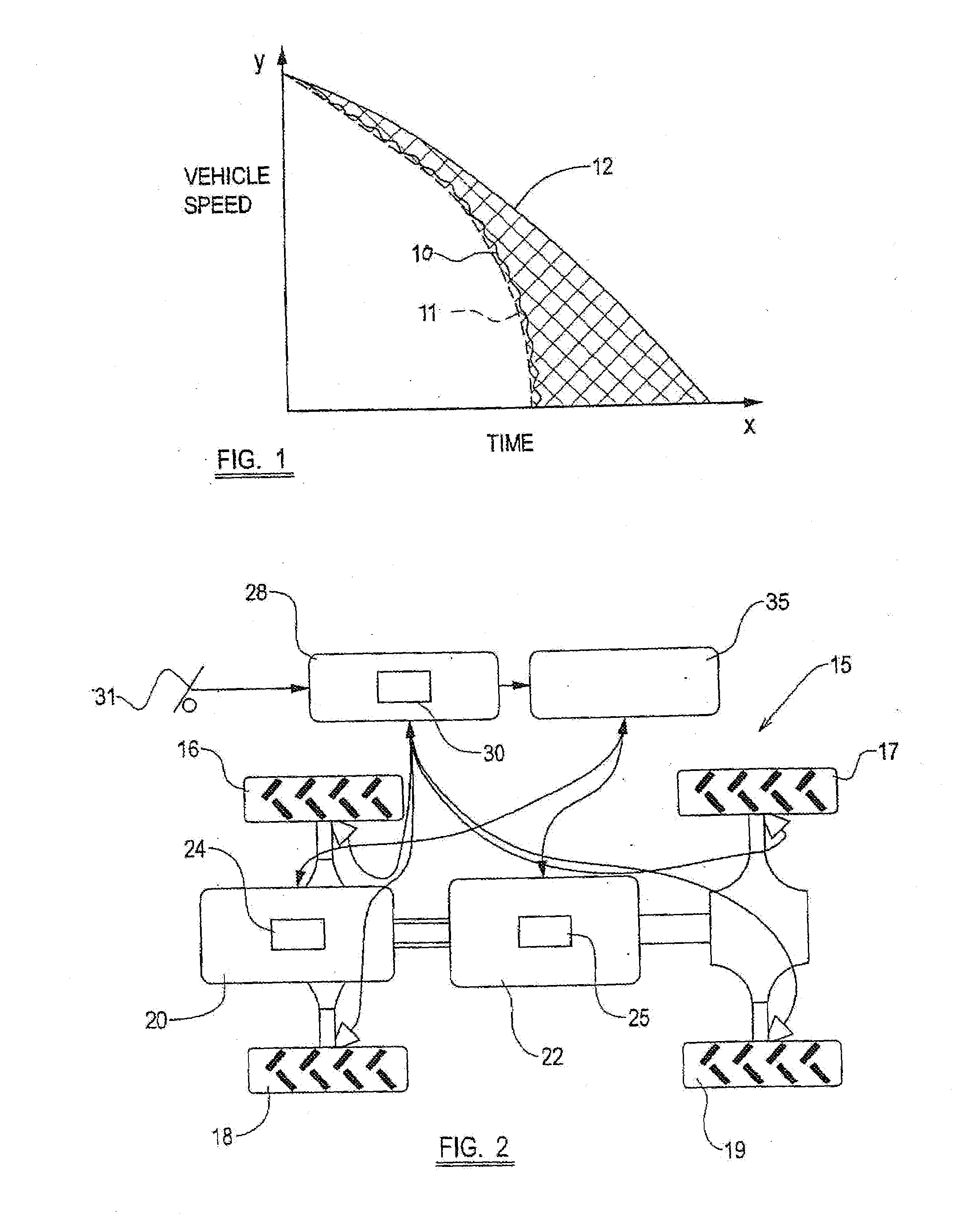
[0037]Referring to FIG. 2, a vehicle 15 includes in this example, four ground wheels 16-19, each of which are drivable from a prime mover 20, which in this example is a conventional engine, via a transmission 22.

[0038]The engine 20 is controlled by an engine controller (such as is known as an engine management system) 24, whilst the transmission 22, in this case a CVT transmission 22, is controlled by a transmission controller 25.

[0039]Each of the wheels 16-19 are braked wheels, there being a braking system 28 with ABS capability, with an ABS controller 30, and in this example a mechanical brake control namely a foot pedal 31. The braking system 28 could be an electrical braking system (EBS) if desired with a non-mechanical brake control, or may have electro-mechanical control, and where a mechanical brake control 31, this could, if desired, be a hand operated control.

[0040]In accordance with the present invention, the vehicle 15 includes a torque controller 35 which is connected to...


PUM


Abstract

A method of braking a vehicle which includes ground engaging wheels, and a braking system with ABS capability and including an operator actuated brake control, the ABS becoming operative in response to the operator actuating the brake control, and upon the braking system sensing the slippage or impending slippage of at least one of the ground wheels relative to the ground, to vary the braking force applied to the at least one of the wheels between, in alternative periods, an applied state in which the braking force is applied, and a released state in which the braking force is released, and characterised in that the method includes applying torque to assist acceleration of the wheel 16-19 at least during periods in which the braking force is released by the ABS.

Description

BACKGROUND TO THE OF INVENTION[0001]This invention relates to a method of braking a vehicle in which a braking force is applied to ground wheels.[0002]More particularly but not exclusively the invention relates to a method of braking large wheels on vehicles, for examples, a tractor or loading and / or excavating machine. By “wheels” we include the wheel hub and tyre mounted on the hub.[0003]Such large wheel vehicles are being designed which are capable of high speed travel e.g. at speeds above 20 mph, on public roads. Accordingly the braking systems of such vehicles are required to comply with standards which apply to heavy road vehicles such as trucks. More particularly there is a requirement for the braking systems of such vehicles to have an ABS capability.[0004]ABS becomes operative in response to an operator actuating a brake control, and upon the braking system sensing the slippage or impending slippage of at least one of the ground wheels relative to the ground. The ABS varies...

Claims


Application Information

Patent Timeline
IPC IPC(8): B60T8/60
CPCB60T8/17616B60T8/3215B60T2201/09B60W2520/26F16H2312/18B60T8/74
Inventor FITTON, GREGORY PETERWILLIAMS, ANDREW ROBERT
Owner JCB LANDPOWER
Learn More