Transmitter and Transmission Circuit

a transmission circuit and transmitter technology, applied in the direction of logic circuit coupling/interface arrangement, pulse manipulation, pulse technique, etc., can solve the problem of prior art, increase the layout area, and the receiver circuit to misread the original signal

Active Publication Date: 2007-06-21
VIA TECH INC
View PDF8 Cites 35 Cited by
  • Summary
  • Abstract
  • Description
  • Claims
  • Application Information

AI Technical Summary

Problems solved by technology

Thus, the receiving circuit receives the signal different from the original one, causing the receiving circuit to misread the original signal.
However, there are disadvantages of the prior art.
First, the prior art uses two transmitters to synthesize one emphasized output signal, which increases the power dissipation and the layout area.
Second, the prior art also needs a clock delay circuit to properly synthesize the emphasized signal, and the clock delay circuit needs an external clock.
However, for realizing such transmitter, the coil structure of the inductor needs a great deal of layout area and the selection of the inductor is not so flexible, which is not convenient.

Method used


Image

  • Transmitter and Transmission Circuit
  • Transmitter and Transmission Circuit
  • Transmitter and Transmission Circuit

Examples


Embodiment Construction

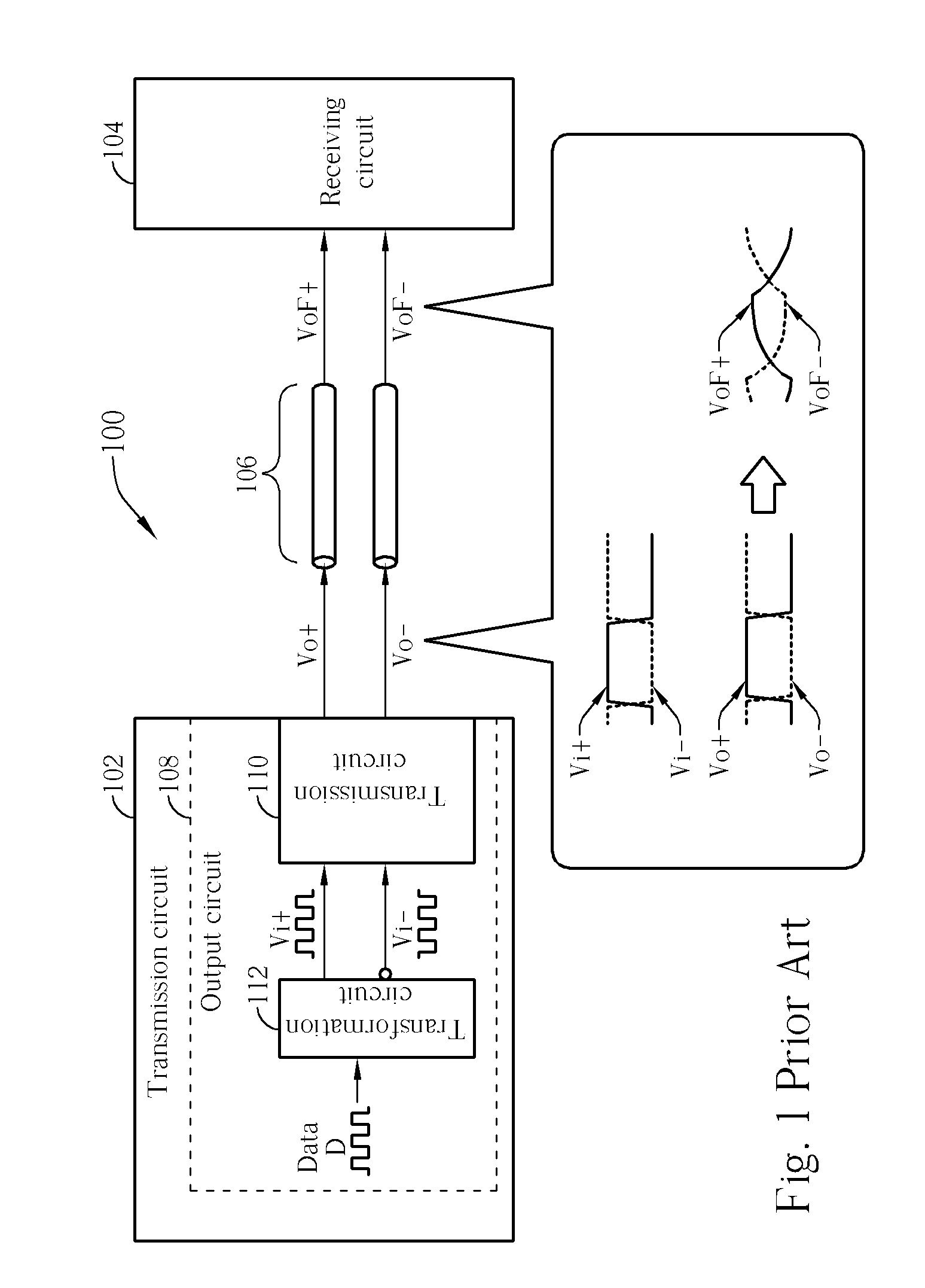
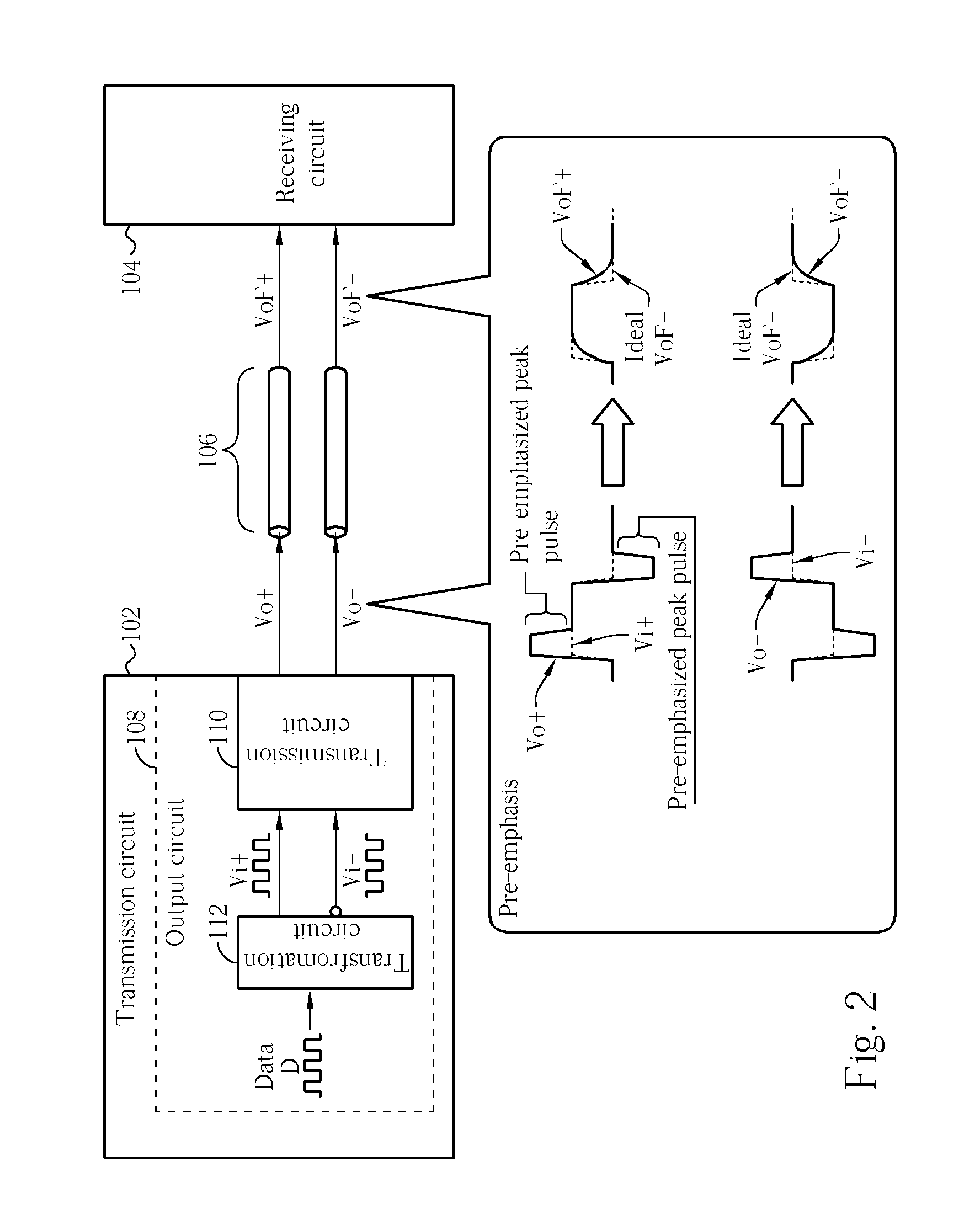
[0022]Please refer to FIG. 1, which is a diagram illustrating a transmission circuitry 102 transmitting data to a receiving circuit 104 in an electronic system 100. As known to those skilled in the art, during a transmission process, differential signals have better resistivity to noise, and less effect on peripheral circuits. Thus, in FIG. 1 and the following content, the related techniques of the present invention are based on differential signal transmission. In the electronic system 100, in order to transmit data in the form of differential signals to the receiving circuit 104, the transmission circuitry 102 comprises an output circuit 108. The output circuit 108 comprises a transformation circuit 112 and a transmission circuit 110. The transmission data serves as an input signal D. The input signal D is then transformed into two differential signals Vi+ and Vi− by the transformation circuit 112, and the transmission circuit 110 outputs the differential signals Vo+ and Vo− accor...


PUM


Abstract

Transmitter and transmission circuit. For realizing a differential transmitter, a switch circuit is connected between two load transistors of two complementary MOS pairs. The switch circuit can have two inductors. When the two complementary MOS pairs are conducting current to drive signal transition at output nodes, the inductors open to make the load transistors stop draining current. Also, the switch circuit can have switch transistor controlled by an edge detector for detecting raising and falling edges of the input signals, such that the switch circuit can make the load transistors stop draining current accordingly. In this way, raising and falling edges of the output signals are emphasized to improve signal propagation.

Description

BACKGROUND OF THE INVENTION [0001]1. Field of the Invention[0002]The present invention provides a transmitter and a transmission circuit, and more particularly, a transmitter and a transmission circuit with the compensation of the equivalent inductance effect for improving the quality of the transmission signals.[0003]2. Description of the Prior Art[0004]In modern society, every kind of information, data, document, video file has been transformed into electrical signals. How to transmit electrical signals for information circulation more effectively has also become the target of the modern information industries. For instance, in the electronic system or network system, data exchange between different circuits, devices, and terminals are accomplished by buses or network transmission lines. Therefore, raising the efficiency of the signal transmission between circuits, maintaining the quality of the signal transmission, and lowering the power dissipation of the signal transmission con...

Claims


Application Information

Patent Timeline
Patent Type & Authority Applications(United States)
IPC IPC(8): H03B1/00
CPCH03K5/1534H03K17/6872H03K19/01721H04L25/0272H04L25/0286
Inventor LIU, CHIH-MIN
Owner VIA TECH INC
Why Eureka
Try Eureka