Simultaneous observation of darkfield images and fluorescence using filter and diaphragm

a filter and diaphragm technology, applied in the field of optical microscopy, can solve the problems of inability to observe living specimens, loss of cell components, and inability to leave artifacts and cell damage that were not present, and achieve the effect of more scattered ligh

Active Publication Date: 2007-06-21
AUBURN UNIV
View PDF52 Cites 12 Cited by
  • Summary
  • Abstract
  • Description
  • Claims
  • Application Information

AI Technical Summary

Benefits of technology

[0018] In some embodiments of the present invention, the diaphragm is a variable diaphragm which varies in size. Changing the size allows more or less light of a certain frequency to pass through the diaphragm. In some embodiments, the variable diaphragm includes a rotate lever for opening and for closing the diaphragm to allow those frequencies that expose more or less of a darkfield image. When opened, the diaphragm allows more light through which results in more scattered light. When the diaphragm is closed less scattered light results.

Problems solved by technology

However, in using electron microscopes, the specimen must be prepared by high-vacuum dehydration and is subjected to intense heat by the electron beam, making observation of living specimens impossible.
The dehydration process also alters the specimen, leaving artifacts and cell damage that were not present in nature.
These procedures, together with electron beam damage caused during the observation of the cells creates the possibility that some components of the cell may be lost or destroyed.
Further, specimen preparation for electron microscopes can take up to two hours each.
The high cost of an electron microscope represents another barrier to its use in the life sciences.
Electron microscopes are large and often require an entire room.
The ultraviolet microscope offers finer resolution and better magnification than an ordinary light microscope, but it has serious disadvantages for the study of living specimens.
Ultraviolet light damages or kills many kinds of living biological specimens, making observation impossible.
Like electron microscopes, the operation of an ultraviolet microscope requires a great deal of skill.
Because ultraviolet light damages the human eye, the image can only be observed by ultraviolet video cameras or specially-equipped still cameras.
Also, the quartz optics required for ultraviolet microscopes are much more expensive than the glass components used in visible light microscopes.
The electron and ultraviolet microscopes available today do not offer a technique for observing living, unaltered biological specimens in real time.
The damage from the electronic beam, from fixing, freezing, exposure to ultraviolet light, and other procedures which occur during observation limits the processes which can be seen by such devices.
For example, the phenomenon of cellular transport cannot be observed in non-living cells by these known devices.
Certain difficulties of the conventional transmitted light fluorescence light microscope made the reflected light fluorescence microscope the instrument of choice by many users.

Method used


Image

  • Simultaneous observation of darkfield images and fluorescence using filter and diaphragm
  • Simultaneous observation of darkfield images and fluorescence using filter and diaphragm
  • Simultaneous observation of darkfield images and fluorescence using filter and diaphragm

Examples


Embodiment Construction

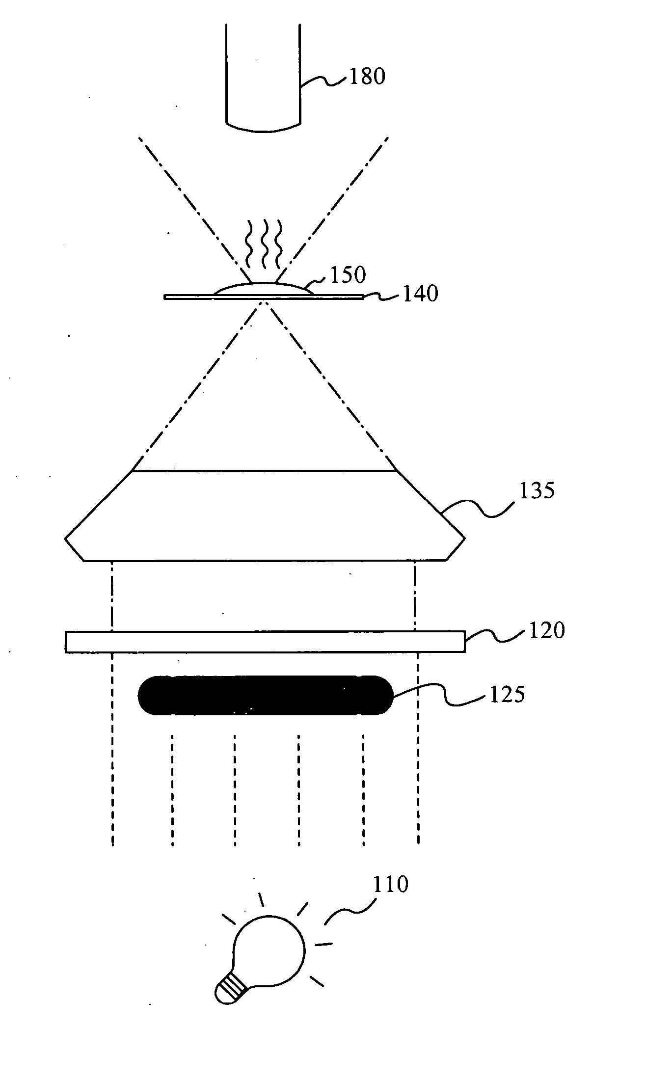
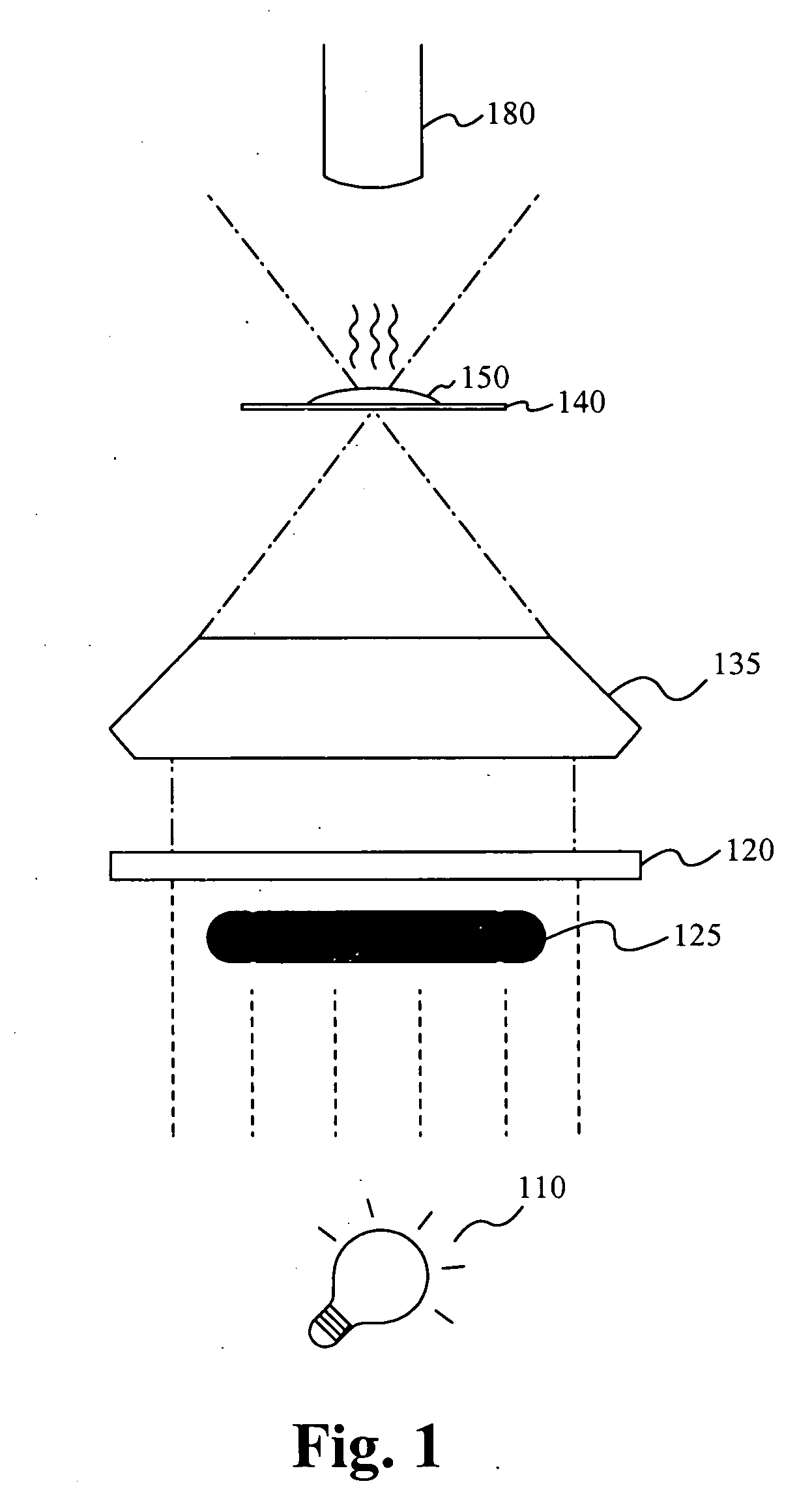
[0032] Darkfield Microscopy and Fluorescence Microscopy techniques are similar at a basic level. Both involve shining incident light from a light source onto a sample to produce images. Both techniques effectively produce high resolution images of small specimen. The present invention allows a scientist the option of using both techniques simultaneously.

[0033] The basic Darkfield Microscopy model involves directing incident light onto a sample at a certain angle. FIG. 1 illustrates the darkfield microscopy technique. A light source 110 directs light at a Darkfield Condenser 135. A central block 125 is used to block the center portion of light, such that only a hollow cylinder of light travels toward the Darkfield Condenser 135. A filter 120 may also be included to filter out certain wavelengths of incident light. The Darkfield Condenser 135 directs the light at some angle toward the slide 140 and the specimen 150. When the light enters the specimen 150, some of it is diffracted and...


PUM


Abstract

An annular diaphragm and filter used for the simultaneous observation of darkfield images and fluorescence. The diaphragm has a variable diameter controlled by a lever and a removable filter. The diaphragm is used to adjust the amount of unfiltered incident light which produces darkfield images when directed on a sample. The removable filter is used to filter light to a particular frequency for producing fluorescence images. An Acousto-Optical Tunable Filter, or other such tunable filter may be used with the diaphragm. A method of using the diaphragm and filter is also disclosed.

Description

RELATED APPLICATIONS [0001] The present application claims priority to U.S. Provisional Patent Application 60 / 749,175, filed on Dec. 9, 2005, and entitled “Simultaneous Observation of Darkfield Images and Fluorescence Using Filter and Diaphragm” to the same inventor under U.S.C. section 119(e). This application incorporates U.S. Provisional Patent Application 60 / 749,175, filed on Dec. 9, 2005, and entitled “Simultaneous Observation of Darkfield Images and Fluorescence Using Filter and Diaphragm” to the same inventor by reference in its entirety.FIELD OF THE INVENTION [0002] The present invention relates generally to the field of optical microscopy. More particularly, the invention relates to the simultaneous observation of Darkfield Images and Fluorescence using a filter and a diaphragm in an optical microscope. BACKGROUND [0003] All living creatures including humans are made of cells. The majority of life forms exist as single cells that perform all functions to continue independen...

Claims


Application Information

Patent Timeline
Patent Type & Authority Applications(United States)
IPC IPC(8): G02B21/06
CPCG01N21/6458G01N2021/8822G02B5/005G02B21/10G02B21/16
Inventor VODYANOY, VITALYPUSTOVYY, OLEG
Owner AUBURN UNIV
Why Eureka
Try Eureka