Automatic braking control device

a control device and automatic technology, applied in the direction of braking systems, brake components, instruments, etc., can solve the problems of inability to obtain the desired deceleration amount, takes longer time to increase the pressure of the brake fluid, etc., to achieve the effect of increasing the accuracy and reliability of the pressure of compressed air, and more reliably limited dispersion in the deceleration amoun

Active Publication Date: 2016-04-26
HINO MOTORS LTD
View PDF24 Cites 0 Cited by
  • Summary
  • Abstract
  • Description
  • Claims
  • Application Information

AI Technical Summary

Benefits of technology

[0028]In the above aspect, the pressure obtaining section obtains the pressure of compressed air in the air tank detected by the pressure detection section. This increases accuracy and reliability of the pressure of compressed air in comparison with a configuration that estimates the pressure of compressed air in the air tank from other information. As a result, dispersion in the deceleration amount will be more reliably limited.

Problems solved by technology

Thus, it takes longer time to increase the pressure of the brake fluid to a predetermined control pressure.
As a result, a desired deceleration amount cannot be obtained before the distance between the vehicle and the object reaches a predetermined value even if the automatic braking control device carries out automatic braking as described above.

Method used


Image

  • Automatic braking control device
  • Automatic braking control device
  • Automatic braking control device

Examples


first embodiment

[0046]According to a first embodiment of the present disclosure, an automatic braking control device such as those mounted on buses and trucks will now be described with reference to FIGS. 1 to 6. At first, the general configuration of a braking system controlled by the automatic braking control device will be described with reference to FIG. 1.

[General Configuration of Braking System]

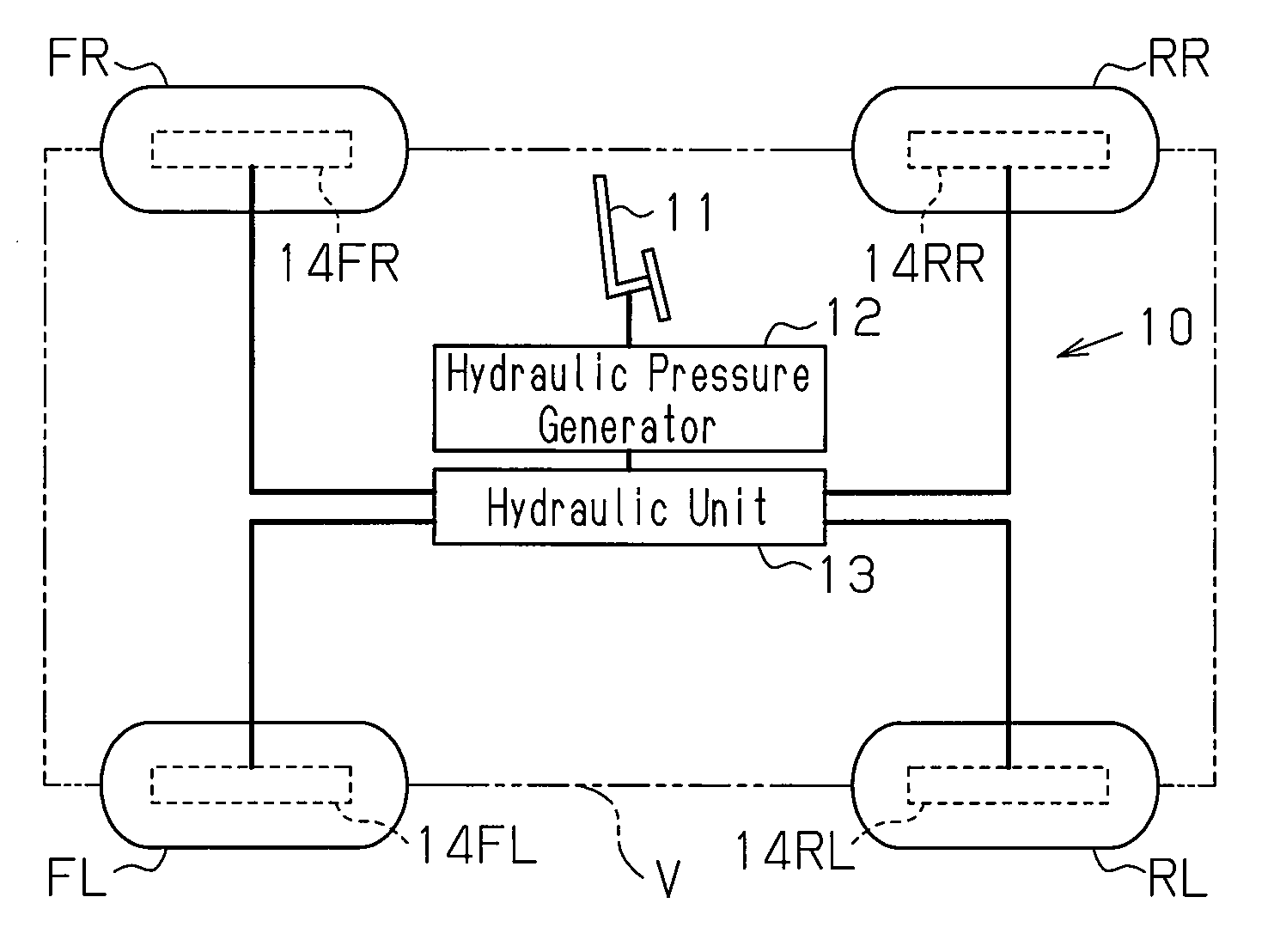
[0047]As shown in FIG. 1, a right rear wheel RR and a left rear wheel RL of a vehicle V and a right front wheel FR and a left front wheel FL of the vehicle V are connected to a braking system 10 that applies braking force to each wheel FR, FL, RR, RL according to driver operation of a brake pedal 11. The braking system 10 is a hydraulic braking system using brake fluid as working fluid.

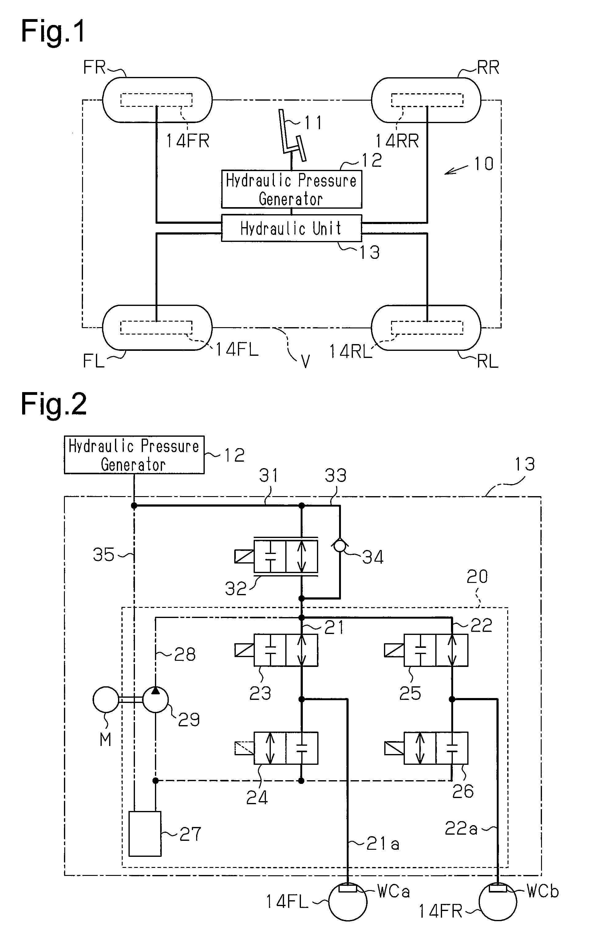
[0048]The braking system 10 includes the brake pedal 11, a hydraulic pressure generator 12, a hydraulic unit 13, and brakes 14FR, 14FL, 14RR, and 14RL attached to the corresponding wheels FR, FL, RR, and RL. The hydrauli...

second embodiment

[0098]According to a second embodiment of the present disclosure, an automatic braking control device mounted on a large-size automobile will now be described with reference to FIGS. 7 to 10. The second embodiment is different from the first embodiment in that the automatic braking control device includes a configuration for estimating the temperature of the brake fluid, and the estimated result is used as an index value of the temperature of the brake fluid. Thus, the difference will be described in detail. The description of other configurations is substituted with the description of the first embodiment.

[Electrical Configuration of Automatic Braking Control Device]

[0099]An electrical configuration of the automatic braking control device mounted on the vehicle V will now be described with reference to FIG. 7.

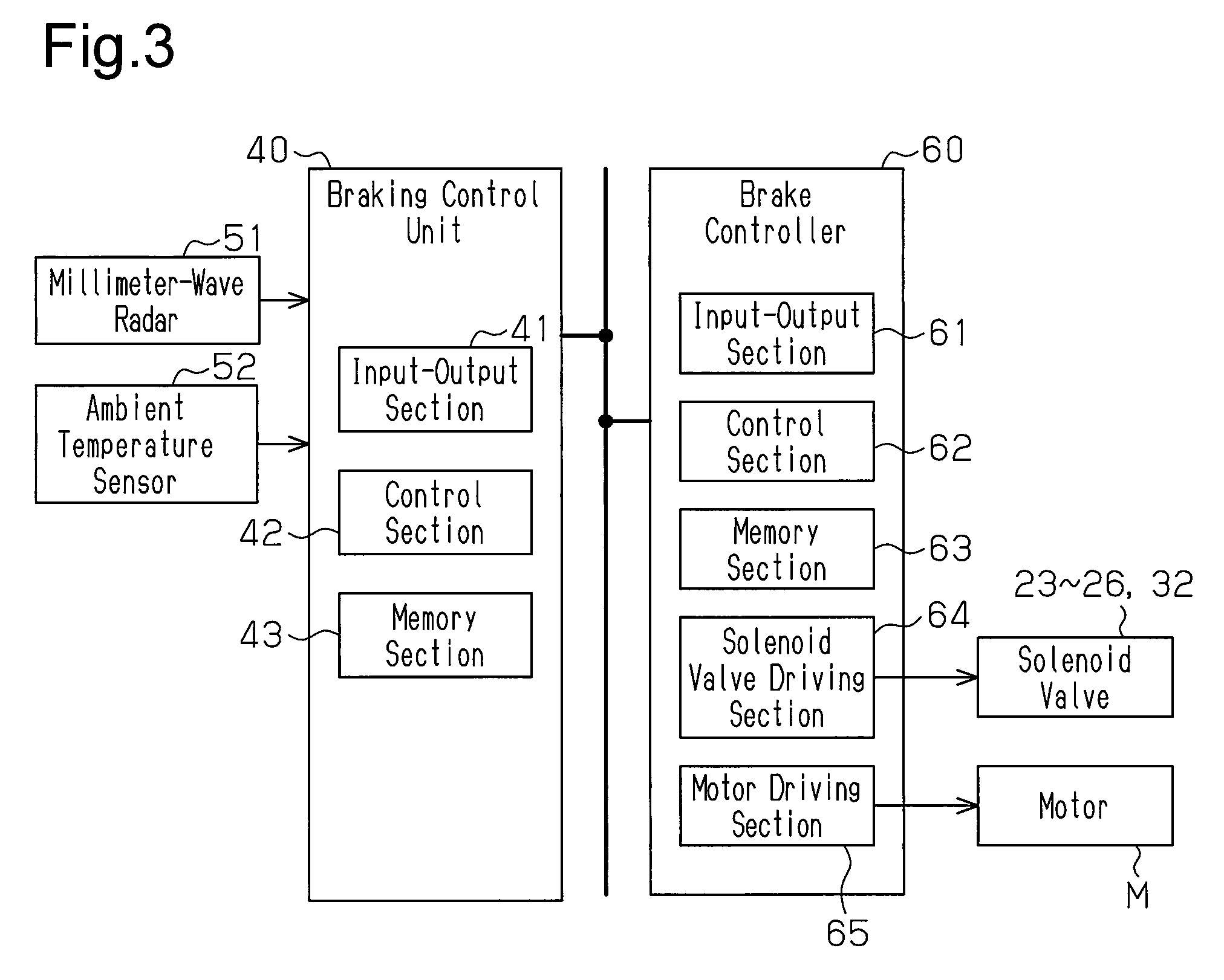
[0100]As shown in FIG. 7, similar to the first embodiment, the braking control unit 40 is connected to the millimeter-wave radar 51 and the brake controller 60. The brake cont...

third embodiment

[0135]A third embodiment of the present disclosure will now be described with reference to FIGS. 11 to 14, in which the automatic braking control device according to the present disclosure is mounted on a large-size automobile such as a bus and a track. An electronic air brake system controlled by the automatic braking control device will be described with reference to FIG. 11. FIG. 11 shows supply passages of compressed air that connect members with solid lines.

[Air Brake System]

[0136]As shown in FIG. 11, a front air tank 111, which supplies compressed air to chambers for front wheels in a vehicle, is connected to a proportional solenoid valve 112 through a supply passage. The proportional solenoid valve 112 is connected to a front chamber 113R for the right wheel and a front chamber 113L for the left wheel through supply passages. The front chamber 113R for the right wheel is connected to a front brake 114R for the right wheel. The front chamber 113L for the left wheel is connecte...


PUM


Abstract

An automatic braking control device includes a temperature obtaining section for obtaining an index value of a temperature of brake fluid, a collision prediction time calculation section for calculating collision prediction time of a vehicle with an object, a collision determination section for determining whether the collision prediction time is less than or equal to a threshold, and a pressure control section for controlling a start timing of pressurization of the brake fluid when the collision prediction time is less than or equal to the threshold. The pressure control section sets the start timing to a first timing when the index value is a first temperature and to a second timing when the index value is a second temperature higher than the first temperature. Time from determination of the collision determination section to the first timing is shorter than time from the determination to the second timing.

Description

CROSS REFERENCE TO RELATED APPLICATIONS[0001]This application is a national stage application under 35 U.S.C. 371 and claims the benefit of PCT Application No. PCT / JP2013 / 065149 having an international filing date of May 31, 2013, which designated the United States, which PCT application claimed the benefit of Japanese Patent Application No. 2012-127540 filed Jun. 4, 2012, and Japanese Patent Application No. 2012-127541 filed Jun. 4, 2012, the disclosure of both the above-identified applications are incorporated herein by reference.FIELD OF THE INVENTION[0002]The present disclosure relates to an automatic braking control device that automatically actuates the brakes on a vehicle with the device when the vehicle anticipates a collision with an object such as another vehicle.BACKGROUND OF INVENTION[0003]For example, as disclosed in Patent Documents 1 and 2, there is a known conventional automatic braking control device in which a braking system automatically actuates the brakes on the...

Claims


Application Information

Patent Timeline
Patent Type & Authority Patents(United States)
IPC IPC(8): G06F19/00B60T7/22B60T13/66B60T13/68B60T17/22B60T8/58
CPCB60T7/22B60T13/662B60T13/686B60T17/221B60T8/58B60T2201/022B60T2201/024
Inventor EZOE, TOSHIKIHOKARI, SATOSHIARITA, MICHITERUYAMAGUCHI, MASAHIROICHINOSE, NAOSHI
Owner HINO MOTORS LTD
Why Eureka
Try Eureka