Linear guide device

a guide device and line-shaped technology, applied in the direction of linear bearings, shafts and bearings, bearings, etc., can solve the problems of unsmooth recirculation of rolling elements, entangled fibers are difficult to be filled into tubes, and entangled fibers are also difficult to be filled into channels, so as to enhance the strength of the outer wall, without increasing the length of the slide member

Active Publication Date: 2007-06-21
CHIEFTECH PRECISION
View PDF12 Cites 10 Cited by
  • Summary
  • Abstract
  • Description
  • Claims
  • Application Information

AI Technical Summary

Benefits of technology

[0006] The primary objective of the present invention is to provide a linear guide device wherein a slide member of which is equipped with a lubricant supply device is capable of lubricating the rolling elements running in the loading zone directly, without increasing the length of the slide member. Thereby, the slide member will lubricate all the rolling elements in a short stroke. The lubricant supply device has a passage connecting to other extending lubricant reservoirs or to the inlet of the lubricant where a tube can be connected and extended to another lubricating reservoir apart from the slide member; a lubricant supply string is provided within and easily filled into the passage or the tube, whereby the lubricant can be transported automatically from the lubricant reservoir to the lubricant supply member; the lubricant reserve ability of the lubricant supply member is therefore increased. The present invention further provides components to enhance the strength of the outer wall of the turnaround channels on the end cap of the slide member.

Problems solved by technology

However, according to the lubricating oil supply system, when the tube is relative long and the hole is small, the entangled fiber is hard to be filled into the tube; also when the supply member, locating inside the slide member, has an anfractuous channel for connecting the lubricant tank; the entangled fiber is also hard to be filled into the channel.
Said connection region and the bottom side of the end cap are thereby facilitated to open and away from their position; such will cause an unsmooth recirculation of the rolling elements.
Conventional seal plate design mounted on the outside of the end cap is fixed on the end cap only and can not improve the strength of the connection between the end cap and the rigid body.

Method used


Image

  • Linear guide device
  • Linear guide device
  • Linear guide device

Examples


Embodiment Construction

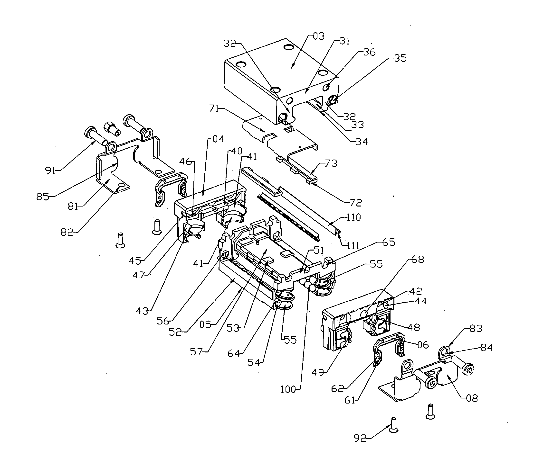
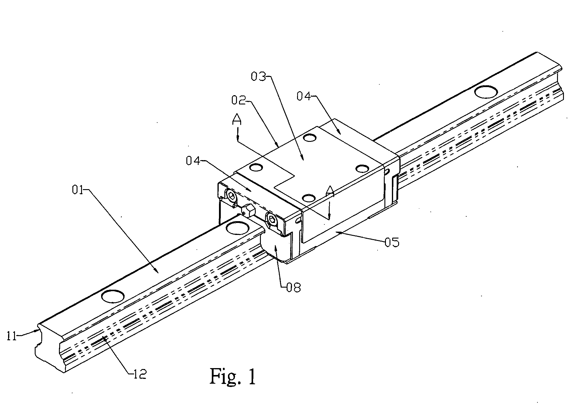
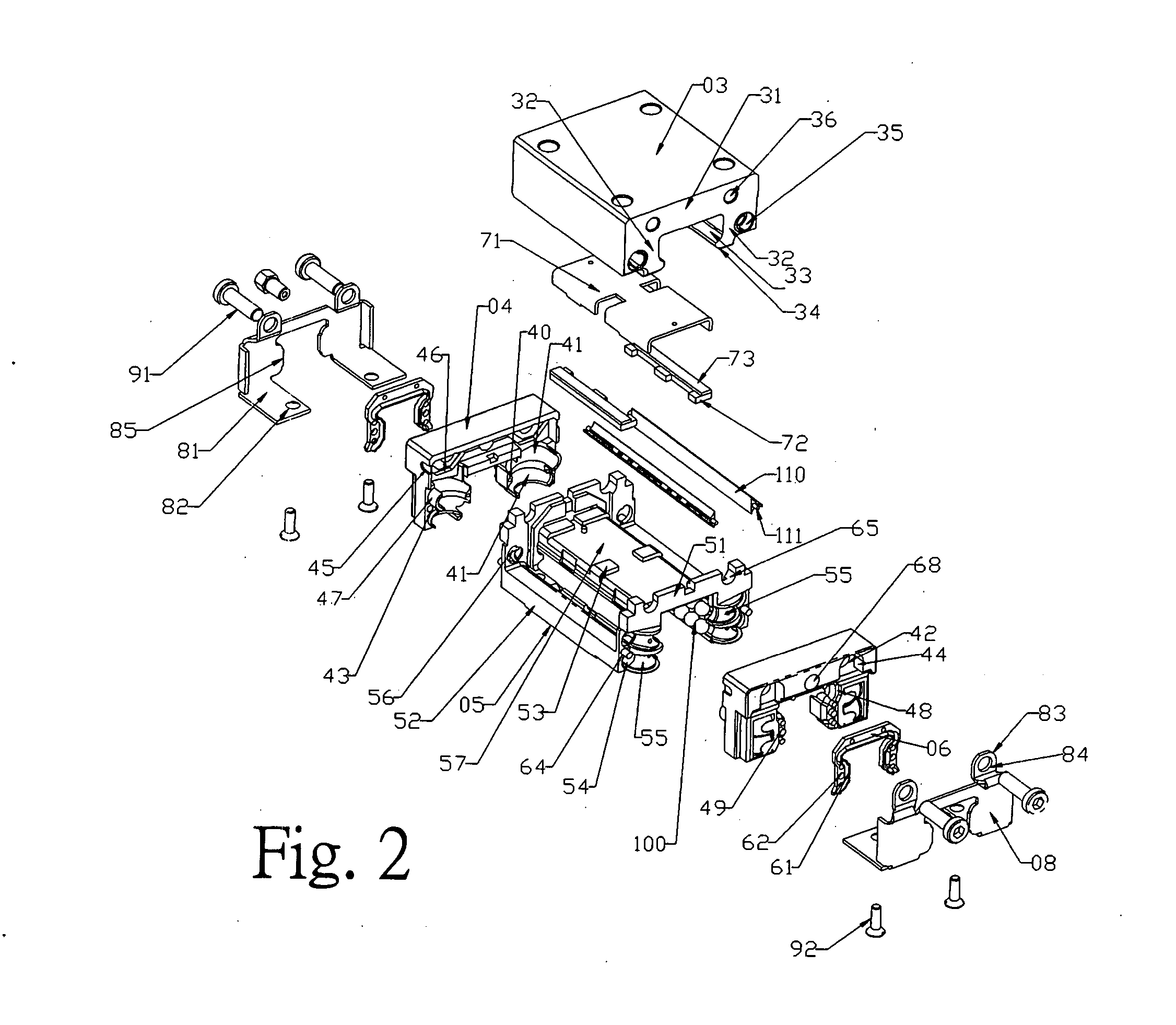
[0019] Referring to FIG. 1, a linear guide device according to the present invention comprises a rail 01, a slide member 02 and a multiple rows of rolling elements 100. The slide member 02 consists of a rigid body 03, a bottom frame 05, a front and a rear end caps 04, a front and a rear end seals 06, a front and a rear reinforce plates 08 and fixing screws 91, 92 as shown in FIG. 2. The rigid body 03 further comprises a flat plate 31 and two leg portions 32 extended downwards therefrom, there are two raceways 33, 34 on the inward surface of each leg portion. The rigid body further comprises through holes, exposed on outer sides of and anear parallel to each upper raceways 33, as return channel 35 for opposed upper raceways 33. There are screw holes 36 on both ends of the rigid body 03 and screw holes 72 on the bottom of the leg portions 32 (shown in FIG. 4).

[0020] The bottom frame 05 is associated under the rigid body 03 and comprises two end plates 51 that are respectively attache...


PUM


Abstract

A linear guide device comprises a rail, at least a slide member and multiple rows of rolling elements. The slide member comprises a rigid body; a bottom frame; a pair of end caps and a pair of reinforce plates. The rail and rigid body provide multiple rows of raceways opposed for the rolling elements. The bottom frame contains a plurality of lubricant reservoirs with lubrication pads inside and directly outstretch from the openings of said lubricant reservoirs to contact with the rolling elements in the raceway zone to supply lubricant on the rolling elements continuously. There are passages or tubes, having lubricating string inside, connecting the extending lubricant reservoirs. Two reinforce plates, each having two extending plates folded and stretched to the bottom of the two leg portions of the rigid body, and are attached on two end caps.

Description

FIELD OF THE INVENTION [0001] The present invention relates to linear guide devices, and more particularly to a linear guide device comprises a longitudinally extended rail, a slide member and a plurality of rows of rolling elements and a lubrication system, therewith the rolling elements roll between the raceway of the slide member and the rail and circulate in the recirculation channel provided by the slide member; a lubrication system provides the lubricant continuously for the required lubrication of rolling elements rolling on the raceways. To enhance the moving speed of the slide member along the rail, a reinforcement design of the outwards surface of the turnaround channel on the end cap is provided. BACKGROUND OF THE INVENTION [0002] A linear guide device comprises a rail, at least a slide member and multiple rows of rolling elements. The rail has multiple of axially extended raceways on its outer surface. The slide member is at least composed of a rigid body, a front and a ...

Claims


Application Information

Patent Timeline
Patent Type & Authority Applications(United States)
IPC IPC(8): F16C29/06
CPCF16C29/0664F16C33/6607
Inventor HSU, MING-CHECHEN, LIH-FEN
Owner CHIEFTECH PRECISION
Why Eureka
Try Eureka