
Optical bi-directional rotary hinge

Inactive Publication Date: 2007-06-21
WSOU INVESTMENTS LLC
View PDF8 Cites 12 Cited by
  • Summary
  • Abstract
  • Description
  • Claims
  • Application Information

AI Technical Summary

Benefits of technology

[0010] According still further to the first aspect of the invention, an optical index matching fluid may be used to fill an air gap between the at least one sending optical guiding element and the at least one receiving optical guiding element to minimize an air-interface reflection on coupling facets of the optical guiding elements.
[0014] Still yet further according to the first aspect of the invention, a coupling facet of the at least one receiving optical guiding element or the at least one sending optical guiding element may be coated with an antireflection coating for reducing reflection losses.
[0020] Still further according to the second aspect of the invention, an optical index matching fluid may be used to fill an air gap between the at least one sending optical guiding element and the at least one receiving optical guiding element to minimize an air-interface reflection on coupling facets of the optical guiding elements.
[0023] According further still to the second aspect of the invention, a coupling facet of the at least one receiving optical guiding element or the at least one sending optical guiding element may be coated with an antireflection coating for reducing reflection losses.

Problems solved by technology

Transmitting an optical signal (e.g., bi-directional data transmission) through a rotary hinge is not an easy task, since uninterrupted optical fibers cannot be used.
A similar problem can be also found in hinges limited in its turning feature, e.g., to a range + / −180° hinges.
In this case, in principle, one can lead optical fibers through the hinge, but then the durability of the optical fibers will be limited.

Method used


Image

  • Optical bi-directional rotary hinge
  • Optical bi-directional rotary hinge
  • Optical bi-directional rotary hinge

Examples


Embodiment Construction

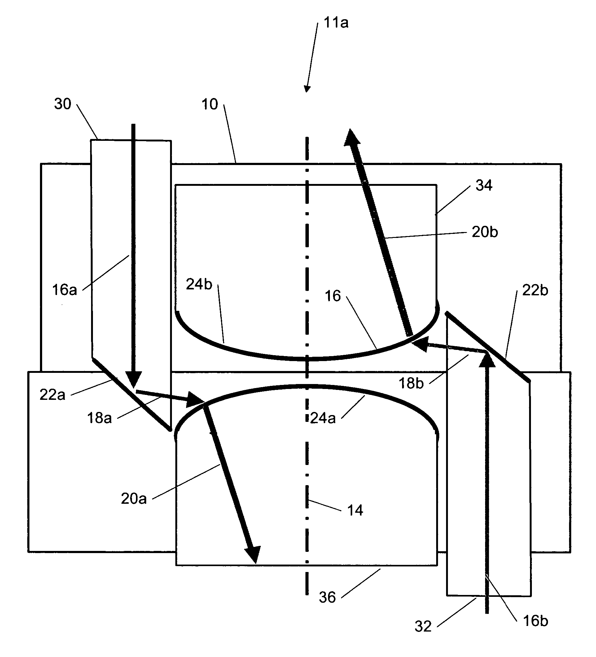
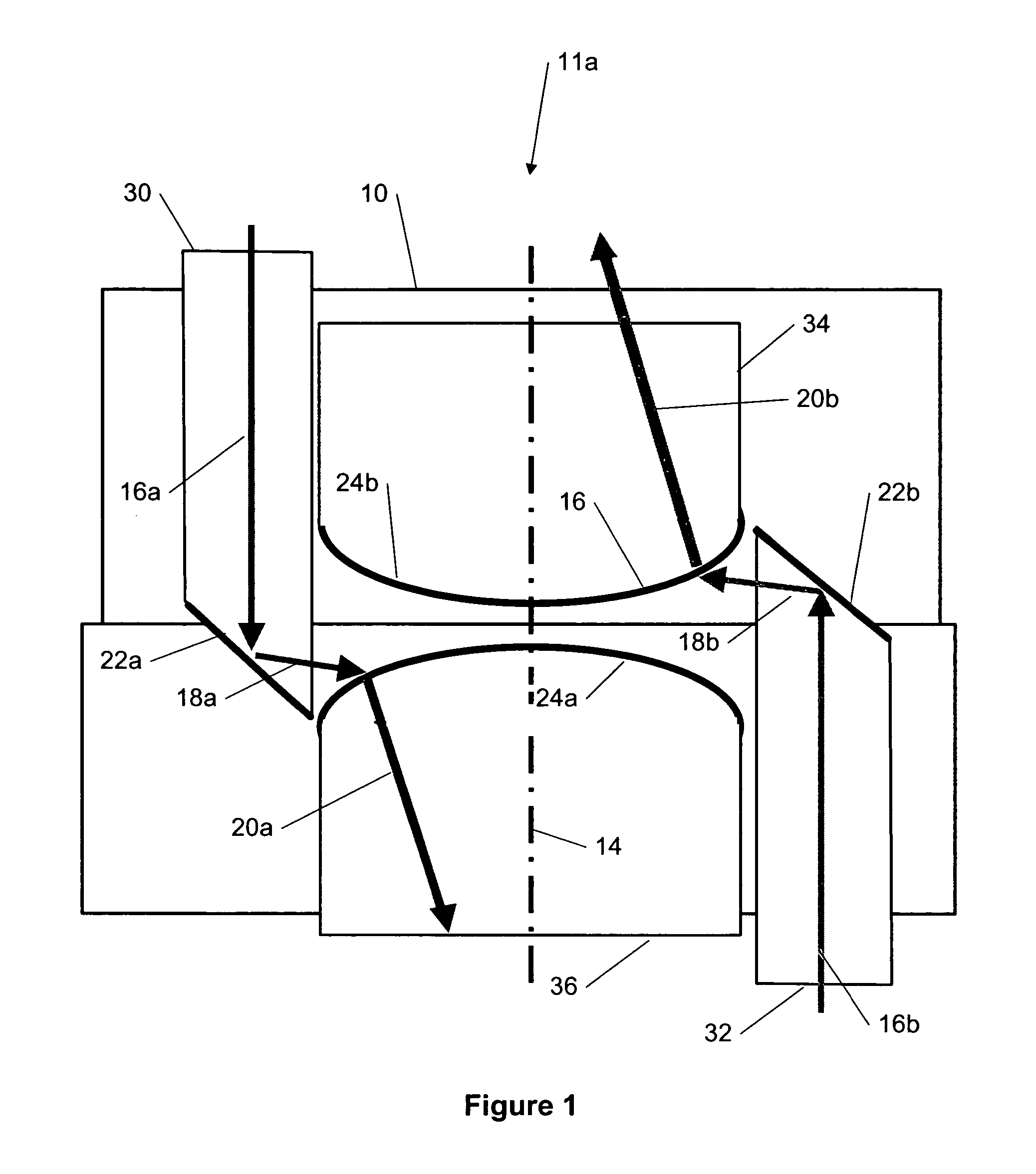
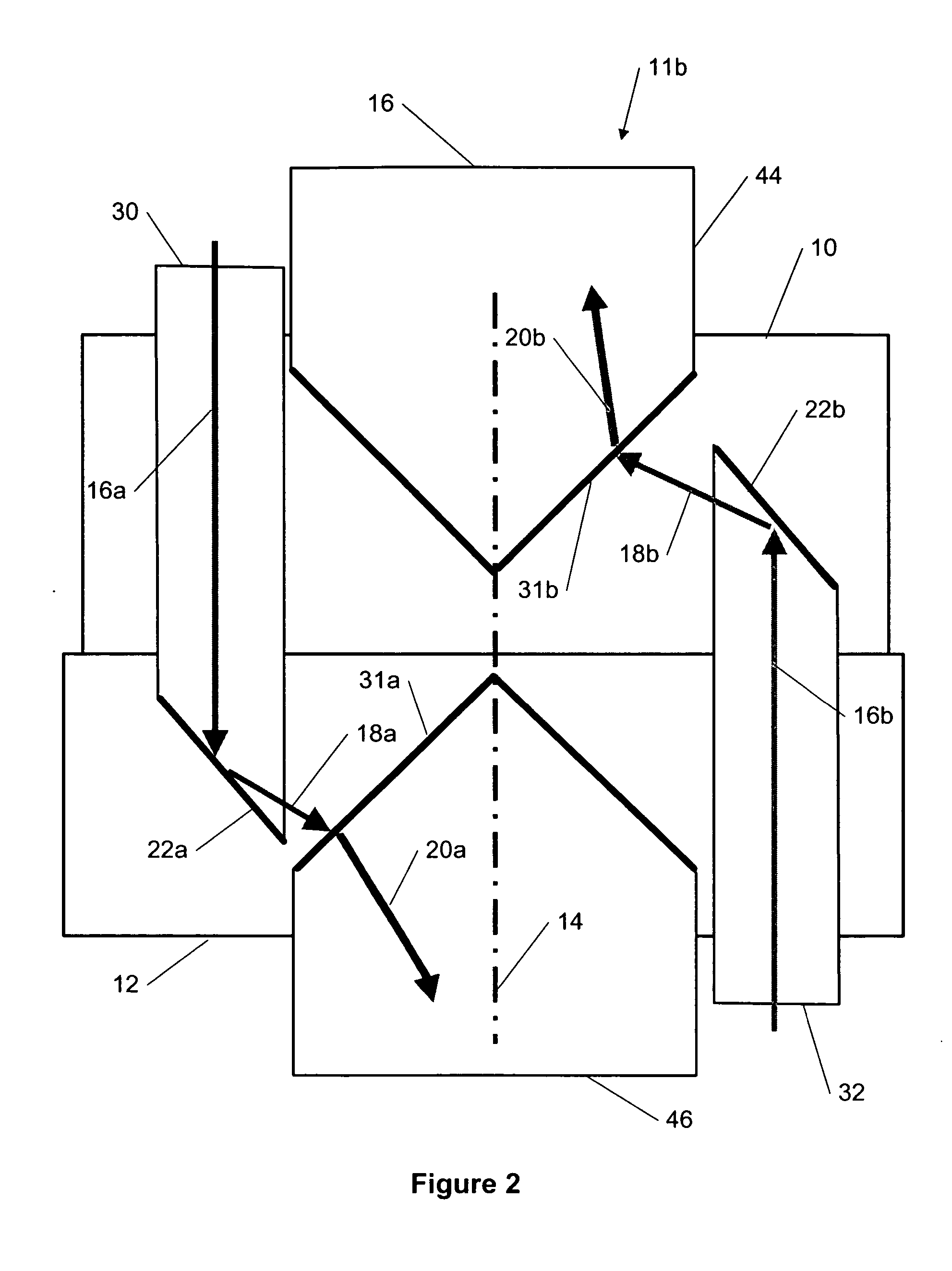
[0040] A new apparatus and method for a rotary hinge for transmitting an optical signal bi-directionally or uni-directionally from one part to another in an electronic device, wherein these parts can rotate relative to each other using the rotary hinge. The optical signal can be transferred from one side to the other side of the hinge independently from light transmitted in the other direction. The hinge can be rotated without angular limitation if no other means (e.g. electrical cables) hinder that. The electronic device can be (but is not limited to) a camera, a camera-phone, a wireless device, a portable electronic device, a mobile terminal, a mobile phone, etc.

[0041] The rotary hinge comprises a first hinge part which is rigidly connected to a first part of the electronic device and a second hinge part which is rigidly connected to a second part of the electronic device, wherein said first and second hinge parts, and therefore the first and the second parts of the electronic de...


PUM


Abstract

The specification and drawings present a new method and apparatus for a rotary hinge for transmitting an optical signal (e.g., comprising data) bi-directionally or uni-directionally from one part to another in an electronic device, wherein these parts can rotate relative to each other using the rotary hinge. The optical signal can be transferred from one side to the other side of the hinge independently from light transmitted in the opposite direction. A sending guiding element (e.g., an optical fiber or a light guide) can rotate around a common rotation axis permanently attached to the side sending the optical signal and the emitted optical beam is directed towards the common rotation axis. The receiving guiding element, which collects the optical beam, is concentrically in the centre (coinciding with the common rotation axis) of the receiving side and permanently attached to it.

Description

TECHNICAL FIELD [0001] The present invention relates generally to opto-electronic bi-directional transmission and, more specifically, to two-channel optical transmission through a rotary hinge. BACKGROUND ART [0002] Transmitting an optical signal (e.g., bi-directional data transmission) through a rotary hinge is not an easy task, since uninterrupted optical fibers cannot be used. [0003] A similar problem can be also found in hinges limited in its turning feature, e.g., to a range + / −180° hinges. In this case, in principle, one can lead optical fibers through the hinge, but then the durability of the optical fibers will be limited. [0004] Bi-directional optical signal transmission is preferable for many practical applications, e.g., in mobile phones, where high-speed data transfer in two directions is required, e.g., where a display and a camera are located in the upper part of the phone and the image handling chip(s) are located in the lower part. DISCLOSURE OF THE INVENTION [0005] ...

Claims


Application Information

Patent Timeline
IPC IPC(8): G02B6/26G02B6/42
CPCG02B6/3604G02B6/43H04M1/0216
Inventor SCHORPP, MARCUSTERVONEN, ARI
Owner WSOU INVESTMENTS LLC
Features
  • Generate Ideas
  • Intellectual Property
  • Life Sciences
  • Materials
  • Tech Scout
  • Unparalleled Data Quality
  • Higher Quality Content
  • 60% Fewer Hallucinations
Learn More