Flow passage structure for refrigerant compressor

a compressor and flow passage technology, applied in the direction of machines/engines, liquid fuel engines, lighting and heating apparatus, etc., can solve the problems of reducing the rigidity of the high-speed cantilever shaft, reducing the aerodynamic efficiency, and the difference in the angle of incidence, so as to reduce the disturbance, reduce the flow loss, and increase the compressive efficiency

Active Publication Date: 2007-06-21
IND TECH RES INST
View PDF4 Cites 31 Cited by
  • Summary
  • Abstract
  • Description
  • Claims
  • Application Information

AI Technical Summary

Benefits of technology

[0021]The two-way flow passage structure of the present invention is helpful to uniformly mix the inter-stage pressure refrigerant with the main-flow refrigerant, thereby efficiently decreasing disturbance of the inter-stage pressure refrigerant to the main-flow refrigerant. As a result, the flow loss can be reduced and the compressing efficiency can be increased.
[0022]Meanwhile, the present invention can shorten the distance between the outlet of the deswirl vane and the inlet of the next stage impeller so as to reduce the length of the overhanging cantilever of the high-speed shaft and increase the rigidity of the high-speed shaft. Therefore, a short flow passage and short rotation axis are achieved, and the compressor can be designed more compactly and fabricated at low cost.

Problems solved by technology

However, if the refrigerant injected in the direction of R2 and the refrigerant from the deswirl vane 14 can't be mixed uniformly, the pressure, temperature and density will be distributed unevenly at each section of the fluid, thereby adversely affecting the angle of the refrigerant coming into the next stage centrifugal compressor impeller and causing incidence angle difference.
Thus, aerodynamic efficiency is reduced.
However, this method not only reduces the rigidity of the high-speed cantilever shaft, but also increases the flow loss.
Thus, such problems as efficiency loss and high material cost are generated.

Method used


Image

  • Flow passage structure for refrigerant compressor
  • Flow passage structure for refrigerant compressor
  • Flow passage structure for refrigerant compressor

Examples


Embodiment Construction

[0026]The following illustrative embodiments are provided to illustrate the disclosure of the present invention, these and other advantages and effects can be apparent to those skilled in the art after reading the disclosure of this specification. The present invention can also be performed or applied by other different embodiments. The details of the specification may be on the basis of different points and applications, and numerous modifications and variations can be devised without departing from the spirit of the present invention.

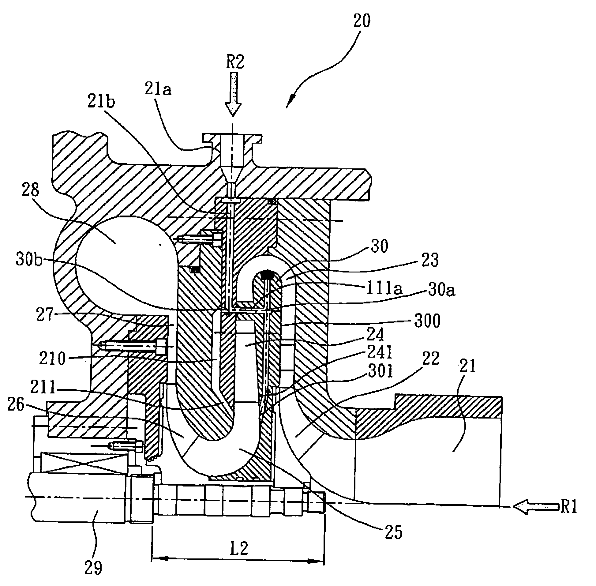
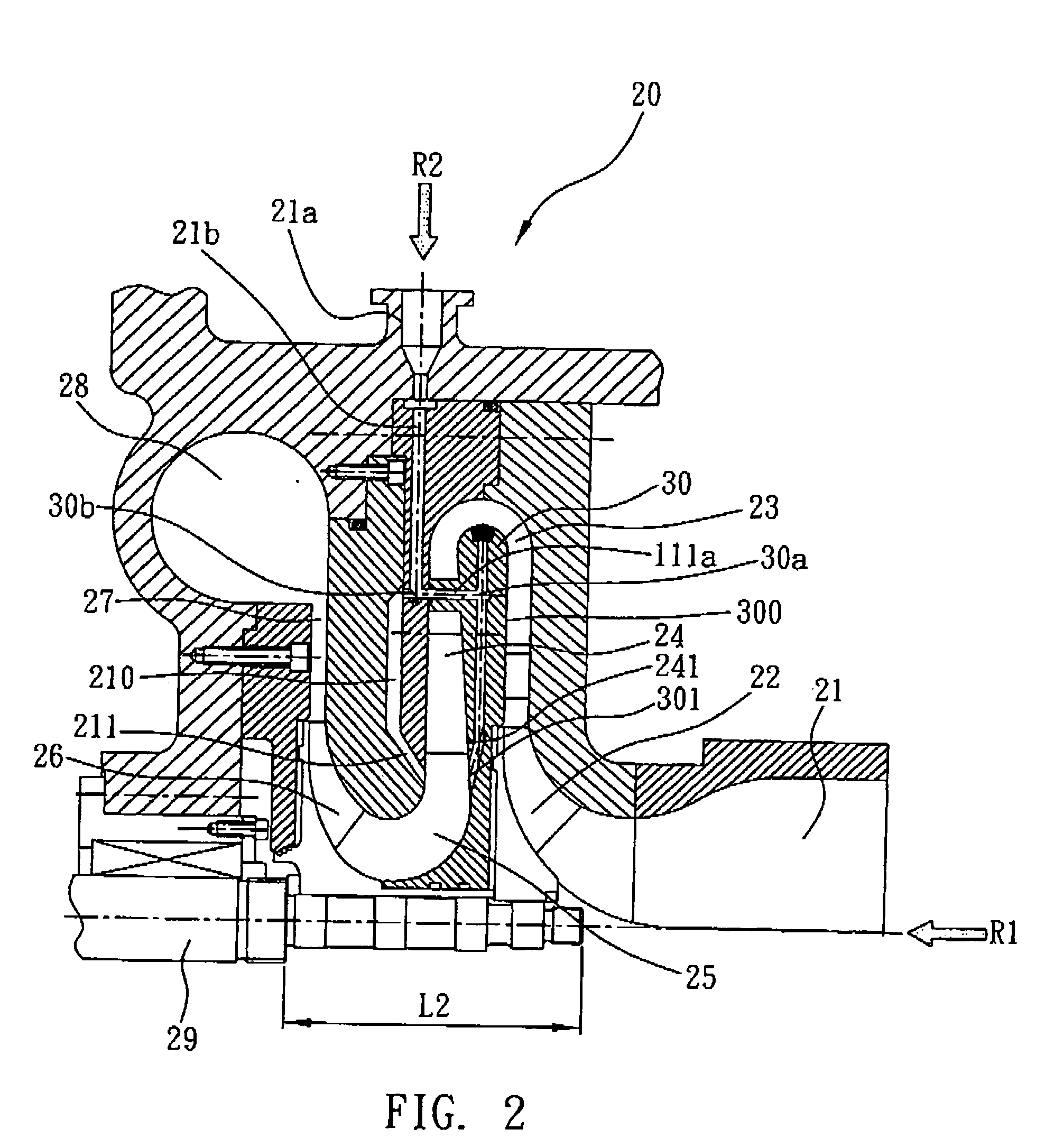
[0027]The flow passage structure of the present invention can be disposed in a multi-stage centrifugal refrigerant compressor. In the present embodiment, the flow passage structure is disposed in a two-stage centrifugal refrigerant compressor, as shown in FIG. 2. Similar to a conventional refrigerant compressor, the two-stage centrifugal refrigerant compressor 20 comprises an inlet 21, a first stage centrifugal compressor impeller 22, a first stage di...


PUM


Abstract

A flow passage structure can be disposed in a multi-stage centrifugal refrigerant compressor having a deswirl vane and a return channel bend. The flow passage structure includes a two-way flow passage having a first outlet and a second outlet, for diverging externally injected refrigerant; a first side discharge flow passage connected to the first outlet of the two-way flow passage and having a first side outlet disposed below the deswirl vane, such that the diverged refrigerant can be discharged into the return channel bend and uniformly mixed with the refrigerant in the return channel bend; and a second side discharge flow passage connected to the second outlet of the two-way flow passage and having a second side outlet disposed below the deswirl, vane, such that the diverged refrigerant tan be injected into the return channel bend and uniformly mixed with the refrigerant in the return channel bend.

Description

BACKGROUND OF THE INVENTION[0001]1. Field of the Invention[0002]The present invention relates generally to flow passage structures for refrigerant compressors, and more particularly, to a flow passage structure that can be used in inter-stage pressure refrigerant injection for a multi-stage centrifugal refrigerant compressor.[0003]2. Description of Related Art[0004]Centrifugal chillers generally comprise centrifugal refrigerant compressors for compressing refrigerant. In practice, for purpose of enhancing refrigeration cycle performance and cooling capability, centrifugal refrigerant compressors having two or more stages are utilized, thereby increasing energy efficiency of centrifugal chillers.[0005]Such a multi-stage centrifugal refrigerant compressor is generally provided with an economizer cycle. Therein, an economizer is used to reduce liquid refrigerant to liquid saturated pressure and flash off a portion of the refrigerant of inter-stage pressure. The flashed off refrigerant ...

Claims


Application Information

Patent Timeline
Patent Type & Authority Applications(United States)
IPC IPC(8): F01C21/00
CPCF04D17/12F04D29/441F25B31/008F04D17/122F04D29/5846F04D29/684
Inventor CHEN, JIING FUCHIANG, CHUNG-PINGCHOW, YUNG-LOYEN, CHENG-CHUNG
Owner IND TECH RES INST
Why Eureka
Try Eureka