Control systems for rotary blood pumps

a control system and rotary technology, applied in the field of improvement of control systems for rotary blood pumps, can solve the problems of partial or complete collapse of the ventricle, deceleration of the patient's ventricle, etc., and achieve the effect of avoiding retrograde flow and minimising the target pump speed

Inactive Publication Date: 2007-06-21
TC1 LLC
View PDF9 Cites 44 Cited by
  • Summary
  • Abstract
  • Description
  • Claims
  • Application Information

AI Technical Summary

Benefits of technology

[0012] In accordance with a second aspect, the present invention consists of a control system for use with rotary blood pumps, wherein the control system includes a selective mode that minimises target pump speed to achieve forward blood flow through both the pump and aortic valve, whilst avoiding retrograde flow.

Problems solved by technology

Rotary blood pumps operating at predetermined fixed pumping rate often tend to over-pump or under-pump blood from the ventricle depending on the physiological needs of the patient and this may lead to deleterious effects on the patient including, but not limited to, suction events or ventricular collapse.
The net result is a partial or complete collapse of the ventricle.

Method used


Image

  • Control systems for rotary blood pumps
  • Control systems for rotary blood pumps
  • Control systems for rotary blood pumps

Examples


Embodiment Construction

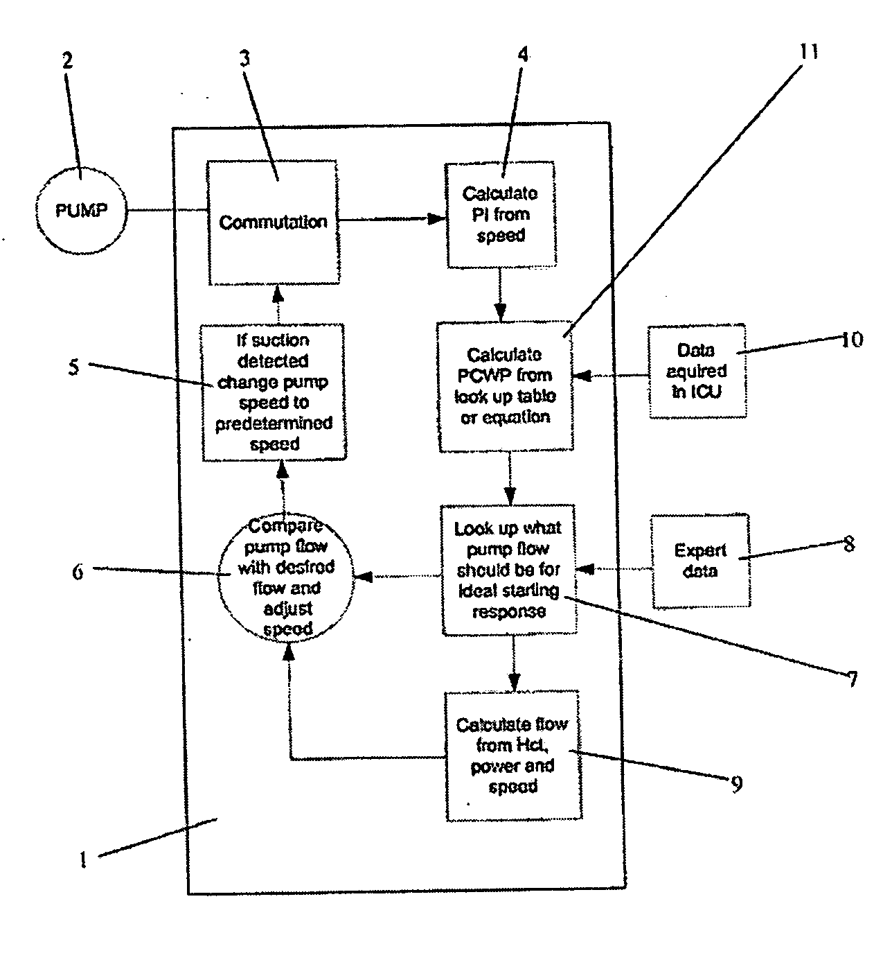
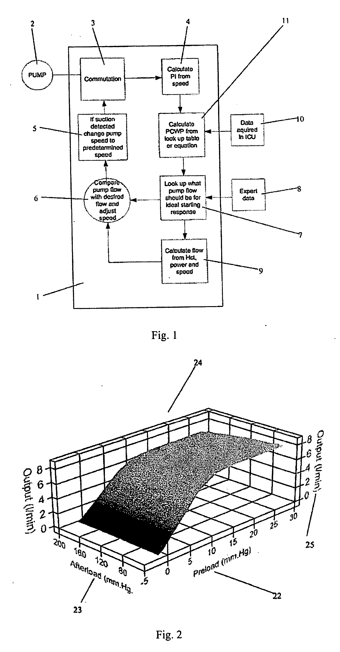
[0022] In a first preferred embodiment of the present invention, as depicted in FIG. 1, a control system 1 is used to control the target speed of a rotary blood pump 2. The rotary blood pump 2 may be implantable or extracorporeal; and may also be a left ventricle assist device. The preferred rotary blood pumps 2 for use with the first embodiment of the present invention are described in: U.S. Pat. No. 6,227,797 (Watterson et al) or U.S. Pat. No. 6,866,625 (Ayre et al) and the descriptions of these inventions are included herein.

[0023] The control system 1 may include several steps or modules to control the target speed of the rotary blood pump 2. Preferably, the control system 1 includes a commutation module 3. The commutation module 3 provides the rotary blood pump 2 with an electromagnetic drive signal to rotate a rotor or impeller (not shown) positioned within the rotary blood pump 2. The commutation module 3 also may detect the actual pumping speed or the actual speed of rotati...


PUM


Abstract

The present invention generally relates to a control system for a rotary blood pump adapted to move blood in a patient. The control system comprises a means for measuring and varying the speed of the pump and a means for measuring the pulsatility index of a patient, and the control system is adapted to maintain the pulsatility index at or near a predetermined value by varying the speed of the pump. The pulsatility index is derived from the amplitude of the actual pump speed over a predetermined time period. Optionally, also, the control system can calculate the second derivative of instantaneous speed of the rotary blood pump and use the calculation of the second derivative of instantaneous speed to detect a suction event, and help prevent it.

Description

TECHNICAL FIELD [0001] The present invention relates to improvements to control systems for a rotary blood pump. BACKGROUND ART [0002] To treat cardiac insufficiency or failure, heart assist devices have been used to assist the heart of a patient. These heart assist devices include various pumping devices. A high level of success has been attributed to a particular group of heart assist devices called rotary blood pumps. [0003] In the past, the rotary blood pumps have used control systems which set the pumping speed at a constant rate. This constant rate would not change for the physiological demands of the patient. Therefore, if a patient was exercising the physiological demands for increased blood supply would not be offset by a matched increased pumping rate or speed of the rotary blood pump. [0004] Therefore, there is a need for a control system that allows a rotary blood pump to match the physiological needs of a patient. [0005] Rotary blood pumps also usually provide a continu...

Claims


Application Information

Patent Timeline
Patent Type & Authority Applications(United States)
IPC IPC(8): A61F2/60A61N1/362
CPCA61M1/101A61M1/1086A61B5/0215A61B5/14535A61B5/4836A61B5/686A61M2205/3334A61M60/148A61M60/104A61M60/422A61M60/216A61M60/178A61M60/538A61M60/531A61M60/569A61M60/585
Inventor AYRE, PETER JOSEPHGLANZMANN, LEE THOMASVON HUBEN, NICHOLAS OLIVER
Owner TC1 LLC
Why Eureka
Try Eureka