Permanent magnet machine and method with reluctance poles and non-identical PM poles for high density operation

a magnet machine and non-identical technology, applied in the field of brushless machines, can solve the problems of low inductance, low efficiency, and inability to achieve high-efficiency magnets, and achieve the effect of reducing current ripple, reducing current ripple, and reducing current rippl

Inactive Publication Date: 2007-06-28
UT BATTELLE LLC
View PDF12 Cites 45 Cited by
  • Summary
  • Abstract
  • Description
  • Claims
  • Application Information

AI Technical Summary

Benefits of technology

[0014] This invention provides a high density PM machine in which reluctance poles are added to permanent magnets (PM's) in a machine rotor to allow enhanced field control. The PM pole portions of one polarity provide enlarged flux paths in relation to flux paths for pole portions of an opposite polarity, with the enlarged flux paths communicating with a core of the rotor so as to increase torque produced by the electric machine.
[0017] The invention provides increased power and torque without increasing the size of the machine.
[0019] The invention is provides a compact electric machine structure for application to electric or hybrid vehicles.

Problems solved by technology

One drawback of the PM motor for the above-mentioned application is that the air gap flux produced by the PM rotor is limited, and therefore, a sophisticated approach is required for high speed, field weakening operation.
Another constraint is that inductance is low, which means that current ripple must be controlled.
It is understood by those skilled in the art that a PM electric machine has the property of high efficiency and high power density, however, the air gap flux density of a PM machine is limited by the PM material, which is normally about 0.8 Teslas and below.
A PM machine cannot operate at an air gap flux density as high as that of a switched reluctance machine.
Therefore, significant flux leakage would occur resulting in a reduction of power density.
In addition, Rosenberg et al. does not teach any additional reluctance poles or reluctance flux paths for producing reluctance torque in such a PM motor.
There are several drawbacks with this approach.
The core loss at high speed is also high, due to the strong PMs, and this is true even when the motor is disconnected from the power supply.
This publication does not disclose the use of field excitation to improve performance.

Method used


Image

  • Permanent magnet machine and method with reluctance poles and non-identical PM poles for high density operation
  • Permanent magnet machine and method with reluctance poles and non-identical PM poles for high density operation
  • Permanent magnet machine and method with reluctance poles and non-identical PM poles for high density operation

Examples


Embodiment Construction

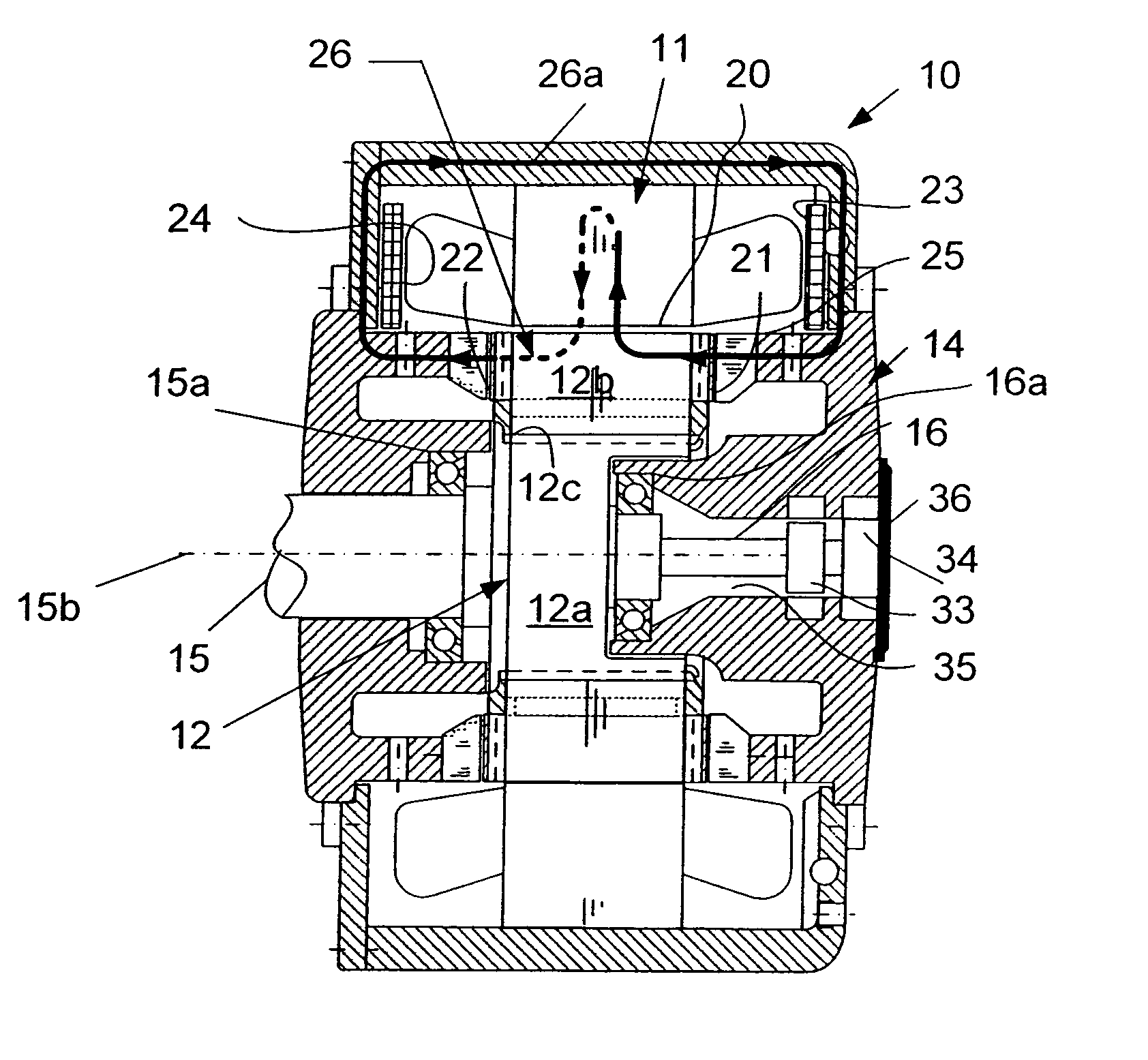
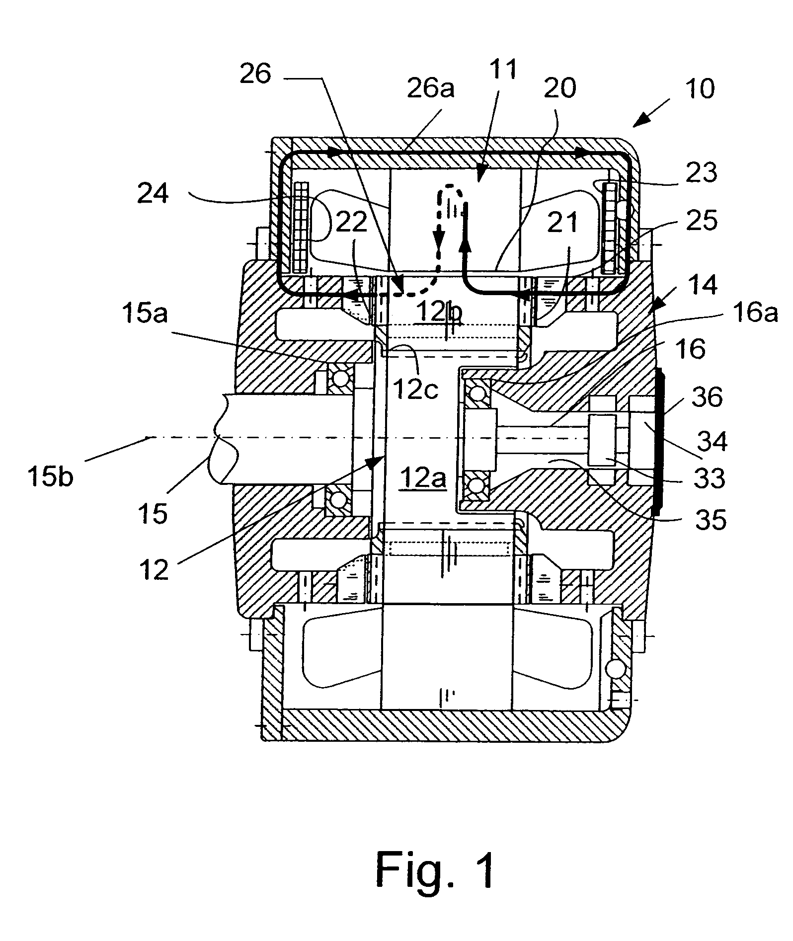
[0034]FIG. 1 shows a longitudinal section view of a radial gap PM machine 10 of the present invention having a ring-shaped stator 11 mounted in a housing assembly 14. The stator has a plurality of stator coils arranged in a manner which is known in the art to produce an AC flux in a radial air gap 20 disposed between the stator 11 and a rotor 12. The rotor 12 is mounted for rotation with a primary drive shaft 15 and a short internal drive shaft 16 that are in turn mounted on bearings 15a, 16a in the housing assembly 14. A shaft encoder 33 and a pump 34 for lubricant for the motor 10 are situated inside a passageway 35 in which in internal shaft 16 is positioned. A housing cover 36 closes the passageway 33.

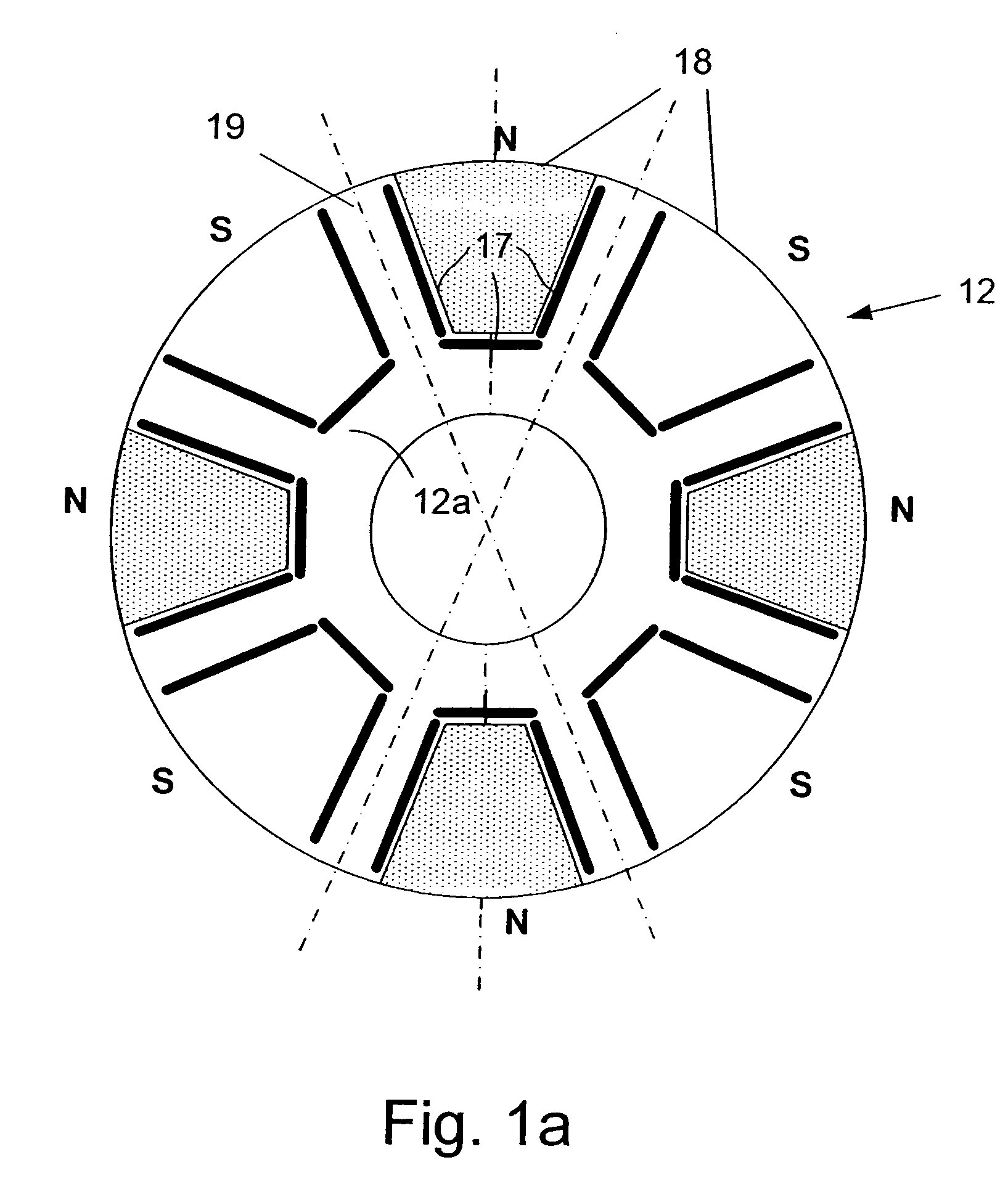
[0035] The rotor 12 is an assembly that has a hub 12a with a plurality of laminations 12b of ferromagnetic material stacked on the hub, keyed to the hub at location 12c and clamped by non-magnetic metal end pieces 12d as further described in U.S. Pat. No. 6,972,504, cited above. T...


PUM


Abstract

A method and apparatus in which a stator (11) and a rotor (12) define a primary air gap (20) for receiving AC flux and at least one source (23, 40), and preferably two sources (23, 24, 40) of DC excitation are positioned for inducing DC flux at opposite ends of the rotor (12). Portions of PM material (17, 17a) are provided as boundaries separating PM rotor pole portions from each other and from reluctance poles. The PM poles (18) and the reluctance poles (19) can be formed with poles of one polarity having enlarged flux paths in relation to flux paths for pole portions of an opposite polarity, the enlarged flux paths communicating with a core of the rotor (12) so as to increase reluctance torque produced by the electric machine. Reluctance torque is increased by providing asymmetrical pole faces. The DC excitation can also use asymmetric poles and asymmetric excitation sources. Several embodiments are disclosed with additional variations.

Description

CROSS-REFERENCE TO RELATED APPLICATION [0001] The benefit of priority based on U.S. Provisional Patent Application No. 60 / 752,695, filed Dec. 21, 2005, is claimed herein. The benefit of priority based on U.S. Provisional Patent Application No. 60 / 806,968, filed Jul. 11, 2006, is also claimed herein. The disclosure of these documents is incorporated herein by reference.STATEMENT REGARDING FEDERALLY SPONSORED RESEARCH [0002] This invention was made with Government support under Contract No. DE-AC05-00OR22725 awarded to UT-Battelle, LLC, by the U.S. Department of Energy. The Government has certain rights in this invention.TECHNICAL FIELD [0003] The field of the invention is brushless machines, including both AC and DC machines, including both motors and generators, and including induction machines, permanent magnet (PM) machines and switched reluctance machines. DESCRIPTION OF THE BACKGROUND ART [0004] There are three major types of brushless electric machines available for the electri...

Claims


Application Information

Patent Timeline
Patent Type & Authority Applications(United States)
IPC IPC(8): H02K21/12H02K23/46H02K21/00
CPCH02K1/2766H02K21/046
Inventor HSU, JOHN S.
Owner UT BATTELLE LLC
Why Eureka
Try Eureka