Power saving device for GPS device

Inactive Publication Date: 2007-06-28
KINPO ELECTRONICS
View PDF5 Cites 32 Cited by
  • Summary
  • Abstract
  • Description
  • Claims
  • Application Information

AI Technical Summary

Benefits of technology

[0008] For improving a conventional power saving device for a GPS device to allow the production cost to be more saved, the present invention is proposed.
[0009] The main object of the present invention is to provide a power saving device for a GPS device, enabling

Problems solved by technology

When a GPS receiver is in a normal o

Method used


Image

  • Power saving device for GPS device
  • Power saving device for GPS device

Examples


Embodiment Construction

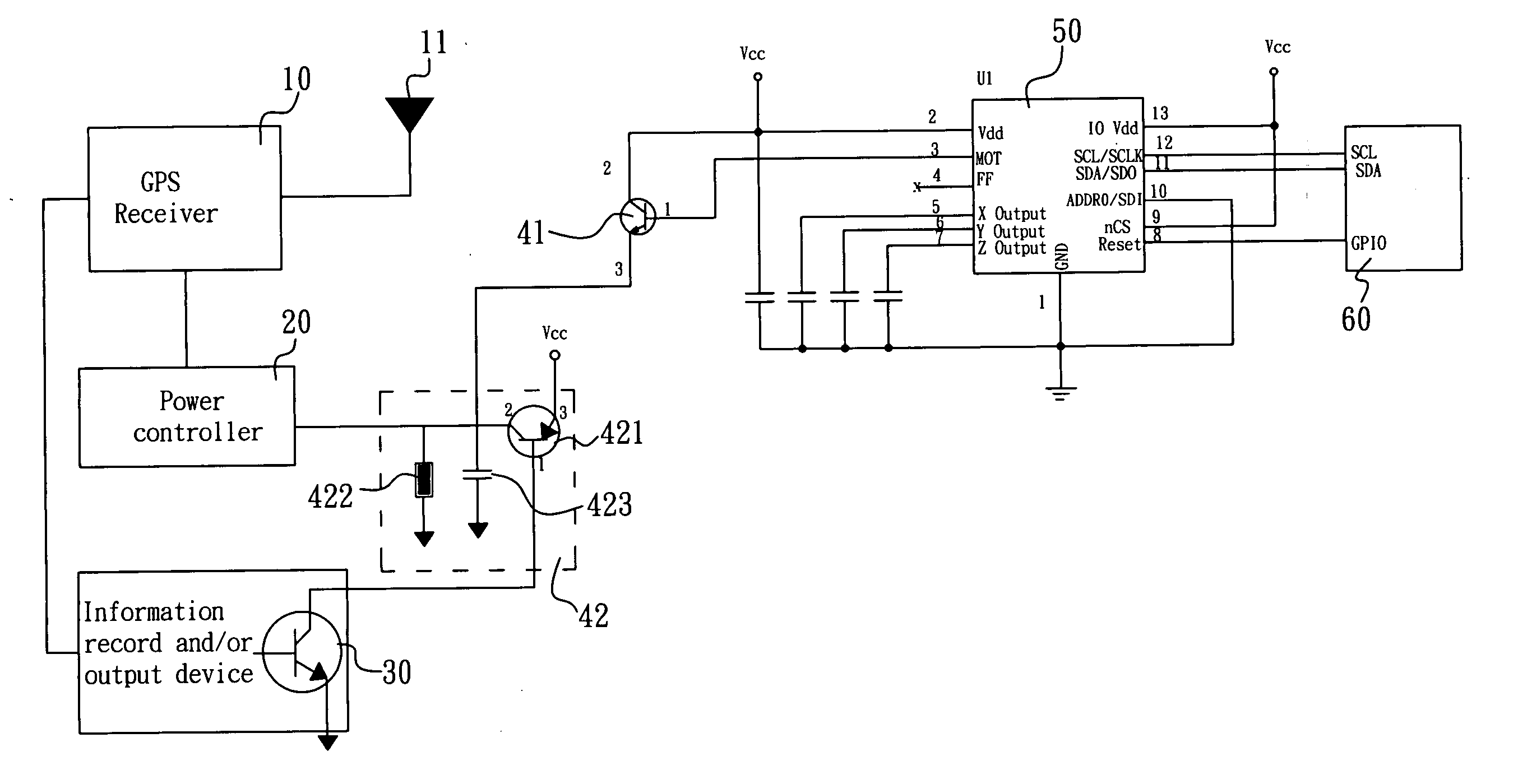
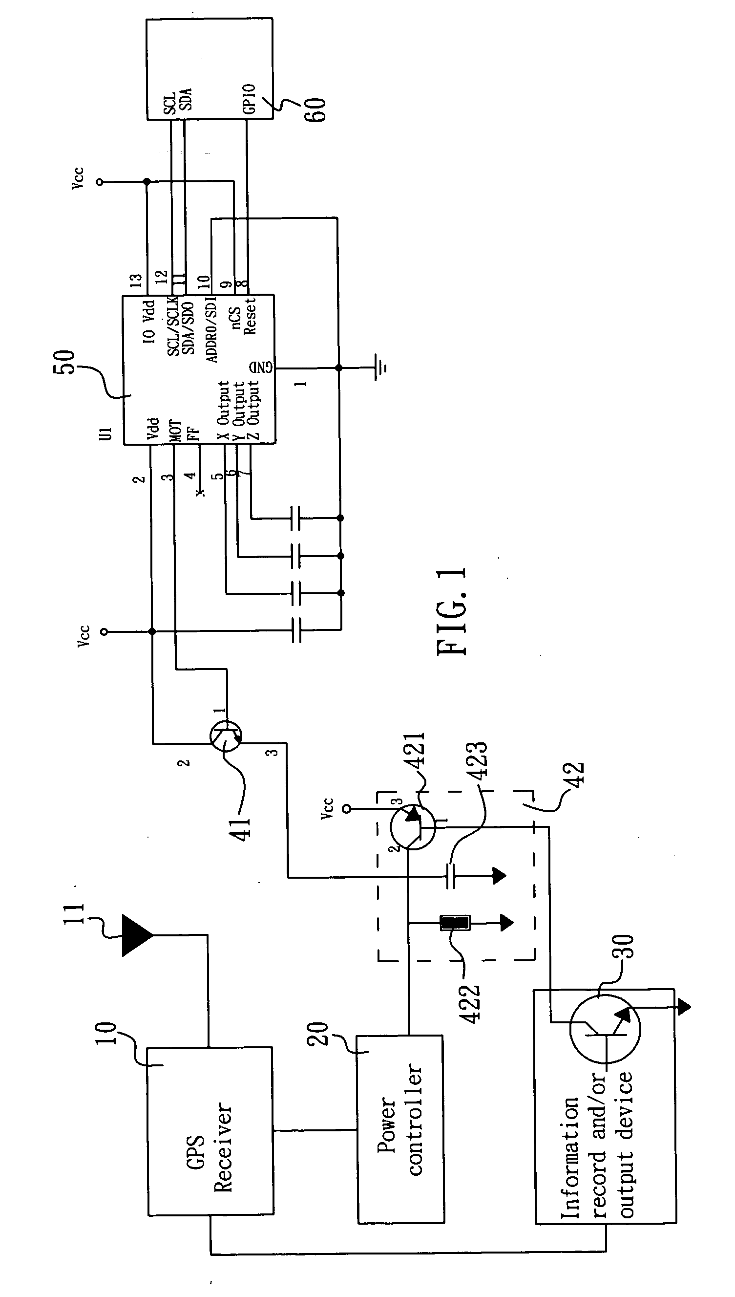
[0013] Please refer to FIG. 1. FIG. 1 is a power saving device for a GPS device of a preferred embodiment according to the present invention. The power saving device comprises a GPS receiver 10 electrically connected to a GPS antenna 11, a power controller 20 and an information record and / or output device 30, in which a time delay controller 42 is respectively electrically connected to the power controller 20, the information record and / or output device 30 and the emitter (second pole) of a first transistor 41. The time delay controller 42 comprises a second transistor 421, a resistor 422 and a capacitor 423. The emitter (third pole) of the second transistor 421 is connected to the power source. The collector (second pole) is electrically connected to the power controller 20. One end of the resistor 422 and one end of the capacitor 423 are grounded, other ends thereof are respectively electrically connected to the collector of the second transistor 421. The information record and / or...


PUM


Abstract

A power saving device for a GPS device is to utilize acceleration of gravity sensor to continue detecting the acceleration variation of the GPS device; if an acceleration value is larger than a threshold value, a GPS signal receiver is then started; if the acceleration value is smaller than the threshold value, the GPS signal receiver is then shut. This allows the GPS device to be power saving and not need to facilitate an extra oscillation switch therein to save the production cost.

Description

BACKGROUND OF THE INVENTION [0001] 1. Field of the Invention [0002] The present invention relates to a GPS device, and more particularly to a power saving device for a GPS device. [0003] 2. Description of Related Art [0004] The upgrading of the manufacturing technology and the functions of an electronic product enable the use of a GPS device to be more popular. There are many types of the GPS device such as a portable GPS device convenient for being used in an individual's mountain climbing and travel, GPS device combined with a cellular phone and GPS device combined with a vehicle allowing a user to realize his position and the direction of the destination that he wants to go if it is operated in coordination with an electronic map. [0005] All general portable GPS devices use a battery to provide electricity. When a GPS receiver is in a normal operation, it is very power consuming. If the GPS device is not moved, it can enter a rather power consuming mode, the power can then be sav...

Claims


Application Information

Patent Timeline
IPC IPC(8): G08B1/08G08B23/00G08G1/123G01S19/19
CPCG01S19/34
Inventor SUN, CHUN-I
Owner KINPO ELECTRONICS
Why Eureka
Try Eureka