Human-machine-interface and method for manipulating data in a machine vision system
What is Al technical title?
Al technical title is built by PatSnap Al team. It summarizes the technical point description of the patent document.
a machine vision system and human-machine interface technology, applied in the field of machine vision systems, can solve the problems of insufficient evidence of object location in the field of view, and cannot be strictly consecutive, and achieve the effects of less expensive, much higher speed, and easy setting up
Inactive Publication Date: 2007-06-28
COGNEX CORP
View PDF99 Cites 71 Cited by
Summary
Abstract
Description
Claims
Application Information
AI Technical Summary
This helps you quickly interpret patents by identifying the three key elements:
Problems solved by technology
Method used
Benefits of technology
[0020] In general, the vision detector is optimally adapted to perform the function of conventional opto-electric detectors. While most of these functions could be performed by a standard machine vision system, the vision detector is less expensive and easier to set up than prior art machine vision systems, and operate at much higher speeds. These systems and methods furthermore make use of multiple perspectives of moving objects, operate without triggers, provide appropriately synchronized output signals, and provide other significant and useful capabilities that will be apparent to those skilled in the art.
[0021] The above-described vision detectors, as well as other machine vision applications, such as readers of symbology (barcodes, etc.), inspection tools and facial identification systems, are generally set up, monitored, adjusted and “debugged” using Human-machine interfaces (HMIs) that employ a graphical user interface (GUI). Once set up, the vision detector and a variety of other stand-alone machine vision systems can often be disconnected from the HMI. Nevertheless, the HMI performs a critical role in the configuration of the system and subsequent analysis of system performance and ability to detect objects and their underlying features. The HMI also allows for monitoring and fault analysis in implementations wherein the detector or other vision system records events and allows playback of the recordings. For these and other purposes, a user-friendly, fully featured and versatile HMI is highly desirable.
[0022] This invention overcomes the disadvantages of prior art systems and methods by providing a Graphical User Interface (GUI) that operates on a Human-Machine Interface (HMI), such as a PC, in connection with a machine vision detector or other machine vision system, which provides a highly intuitive and industrial machine-like appearance and layout. The GUI includes a centralized image frame window surrounded by panes having buttons and specific interface components that the user employs in each step of a machine vision system set up and run a new machine vision job. One pane allows the user to view and manipulate a recorded filmstrip of image thumbnails taken in a sequence, and provides the filmstrip with specialized highlighting (colors or patterns) that indicate useful information about the underlying images. The filmstrip is provided with controls to record, playback and scroll through thumbnails that are simulative of consumer video recording appliances to provide a more-intuitive interface. The filmstrip controls include a selector that allows the user to switch between image modes.
Problems solved by technology
These frames may not be strictly consecutive, however, because as the object passes through the field of view there may be some viewing perspectives, or other conditions, for which the evidence that the object is located in the field of view is not sufficient.
Method used
Image
Click on the blue label to locate the original text in one second.
Reading with bidirectional positioning of images and text.
Examples
Embodiment Construction
[0045] A. Implementation of an Exemplary Machine Vision Detector
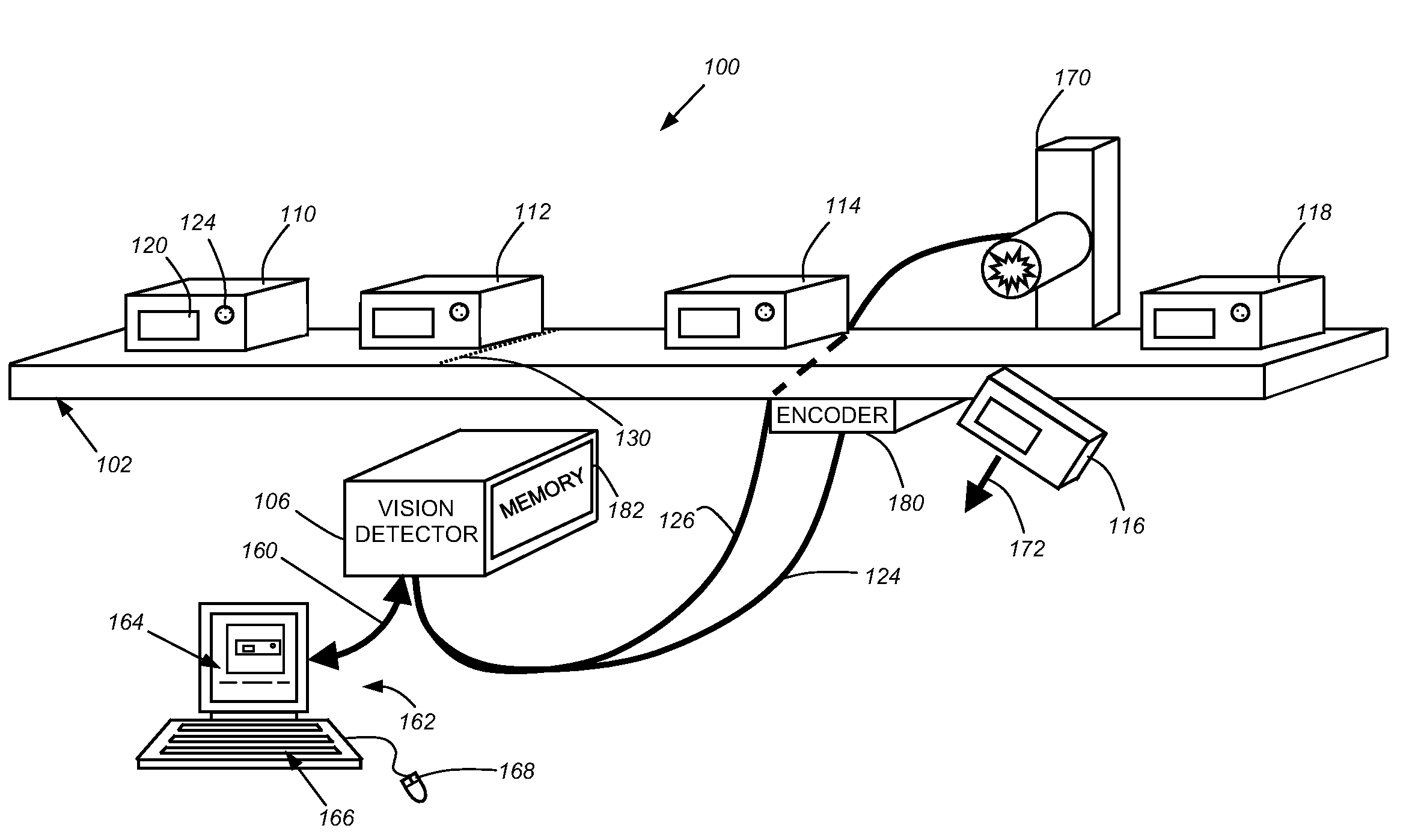
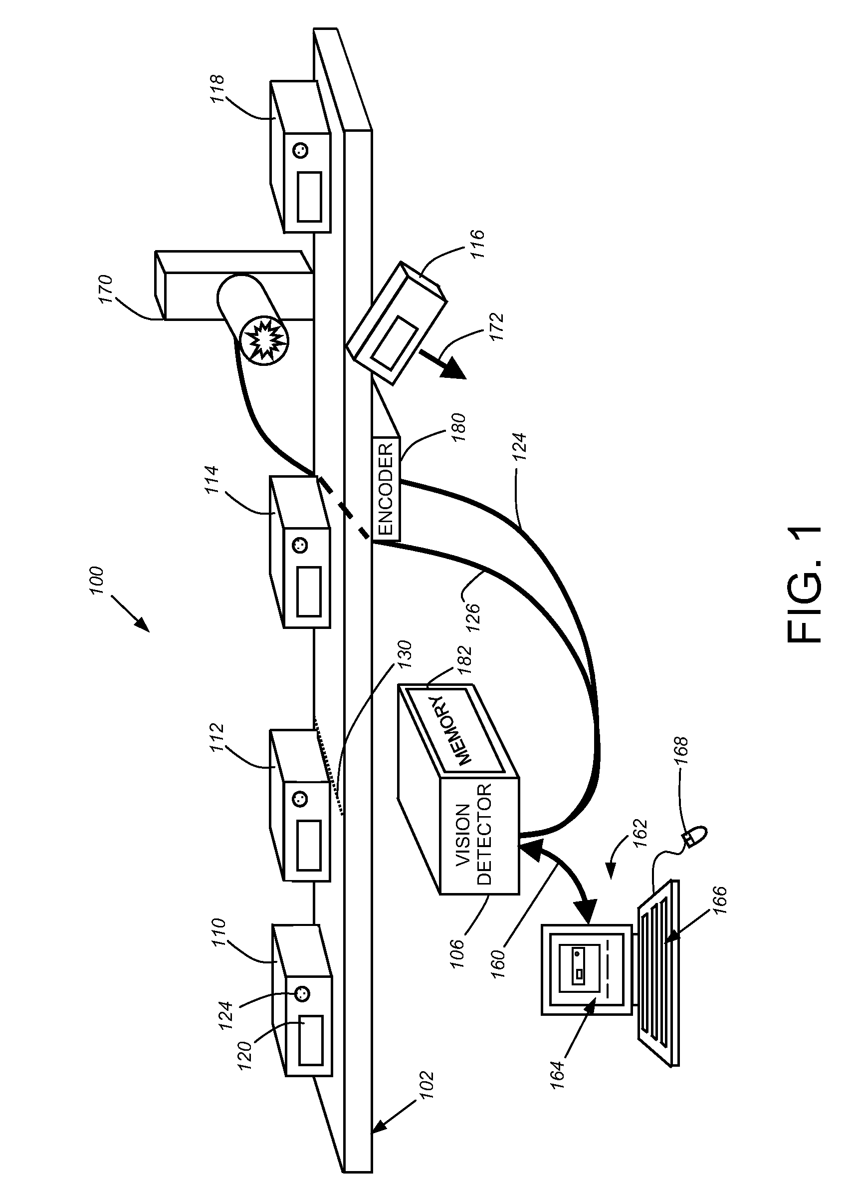
[0046]FIG. 1 shows an example of an exemplary machine vision system to which the teachings of this invention may be applied. The system is a vision detector system 100 as described above, and as set forth generally in the above-incorporated, U.S. Published Patent Application No. US200550275831A1, entitled METHOD AND APPARATUS FOR VISUAL DETECTION AND INSPECTION OF OBJECTS, by William M. Silver. It should be noted that, while this Description references a vision detector as the exemplary operative machine vision implementation, the teachings of an HMI described and claimed herein are expressly applicable to a wide range of vision systems. Thus, the HMI functions and layout described herein should be taken as broadly applicable to any system requiring setup, monitoring, feedback of inspection data and the like. Such systems include, but are not limited to, the exemplary vision detector, a more complete machine vision ins...
PUM
Abstract
This invention provides a Graphical User Interface (GUI) that operates in connection with a machine vision detector or other machine vision system, which provides a highly intuitive and industrial machine-like appearance and layout. The GUI includes a centralized image frame window surrounded by panes having buttons and specific interface components that the user employs in each step of a machine vision system set up and run procedure. One pane allows the user to view and manipulate a recorded filmstrip of image thumbnails taken in a sequence, and provides the filmstrip with specialized highlighting (colors or patterns) that indicate useful information about the underlying images. The system is set up and run are using a sequential series of buttons or switches that are activated by the user in turn to perform each of the steps needed to connect to a vision system, train the system to recognize or detect objects/parts, configure the logic that is used to handle recognition/detection signals, set up system outputs from the system based upon the logical results, and finally, run the programmed system in real time. The programming of logic is performed using a programming window that includes a ladder logic arrangement. A thumbnail window is provided on the programming window in which an image from a filmstrip is displayed, focusing upon the locations of the image (and underlying viewed object/part) in which the selected contact element is provided.
Description
CROSS-REFERENCE TO RELATED APPLICATIONS [0001] The present application is a continuation-in-part of commonly assigned copending U.S. patent application Ser. No. 11 / 138,025 which was filed, May 26, 2005, by William M. Silver, et al., for a METHOD AND APPARATUS FOR AUTOMATIC VISUAL DETECTION, RECORDING, AND RETRIEVAL OF EVENTS, which is a continuation-in-part of commonly assigned, copending U.S. patent application Ser. No. 11 / 059,512, which was filed Feb. 16, 2005, by William M. Silver, et al., for a METHOD AND APPARATUS FOR AUTOMATIC VISUAL DETECTION, RECORDING, AND RETRIEVAL OF EVENTS, which is a continuation-in-part of commonly assigned, copending U.S. patent application Ser. No. 10 / 865,155, which was filed on Jun. 9, 2004, by William M. Silver for a METHOD AND APPARATUS FOR VISUAL DETECTION AND INSPECTION OF OBJECT, the teachings of which are all hereby incorporated by reference.BACKGROUND OF THE INVENTION [0002] 1. Field of the Invention [0003] This invention is related to machin...
Claims
Application Information
Patent Timeline
Application Date:The date an application was filed.
Publication Date:The date a patent or application was officially published.
First Publication Date:The earliest publication date of a patent with the same application number.
Issue Date:Publication date of the patent grant document.
PCT Entry Date:The Entry date of PCT National Phase.
Estimated Expiry Date:The statutory expiry date of a patent right according to the Patent Law, and it is the longest term of protection that the patent right can achieve without the termination of the patent right due to other reasons(Term extension factor has been taken into account ).
Invalid Date:Actual expiry date is based on effective date or publication date of legal transaction data of invalid patent.
Patent Type & Authority Applications(United States)