
Measurement method and apparatus, exposure apparatus, and device manufacturing method

Inactive Publication Date: 2007-06-28
CANON KK
View PDF24 Cites 13 Cited by
  • Summary
  • Abstract
  • Description
  • Claims
  • Application Information

AI Technical Summary

Benefits of technology

[0010] The present invention is directed to a measurement method that can highly precisely measure an optical characteristic of a target optical system using a simple, small and inexpensive interferometer.

Problems solved by technology

This conventional measurement method has a problem in a poor reproducibility of measurement due to a difficult SEM operation and errors in a resist application and a development.
However, the conventional interference method that uses a Fizeau interferometer, a Twyman-Green interferometer, or the like makes an overall system's structure complex, thus implying a large-size and high-cost problem.
Thus, it is difficult to mount the interferometer on an exposure apparatus, and the conventional interference method is not viable.
However, a measurement of a wavefront aberration using the PDI or LDI does not consider a polarization state of a light incident upon an image side measurement pattern (or an image side slit), and causes a measurement error in measuring a wavefront aberration of an optical system having a large numerical aperture (“NA”).
Thus, the polarized incident light causes an error in the LDI measurement, because a difference in diffracted wavefronts from the pair of slits becomes an error of the reference wavefront.

Method used


Image

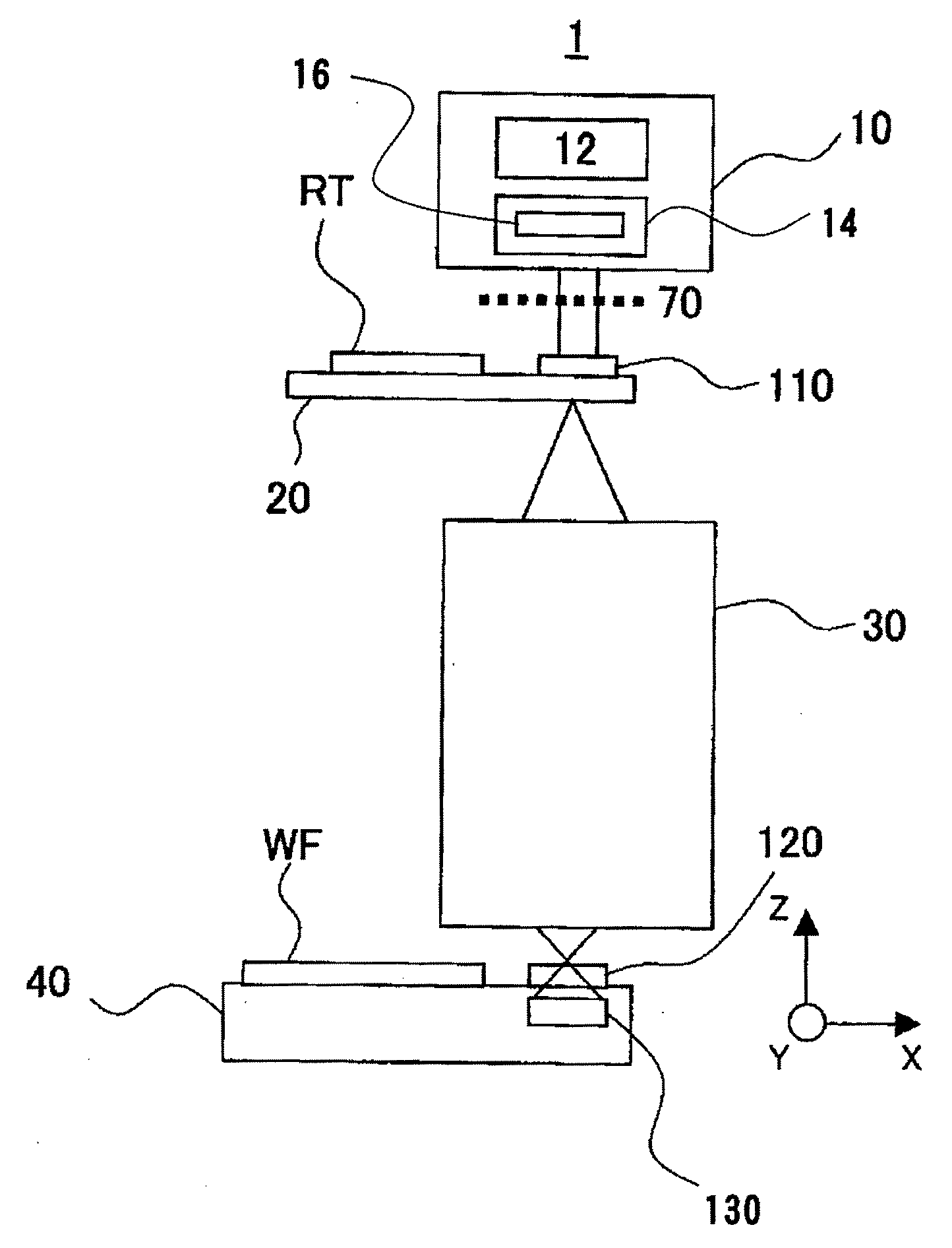
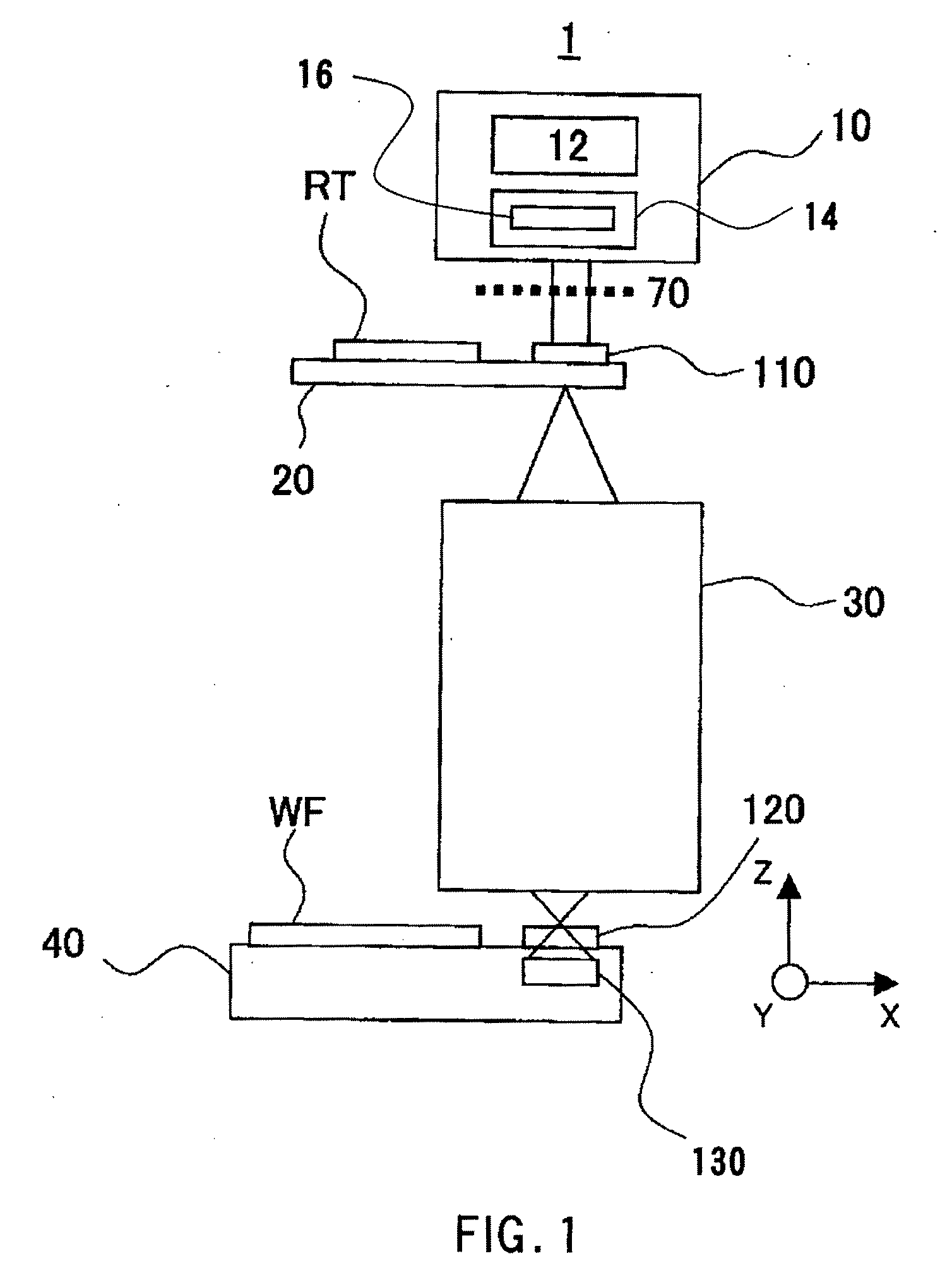
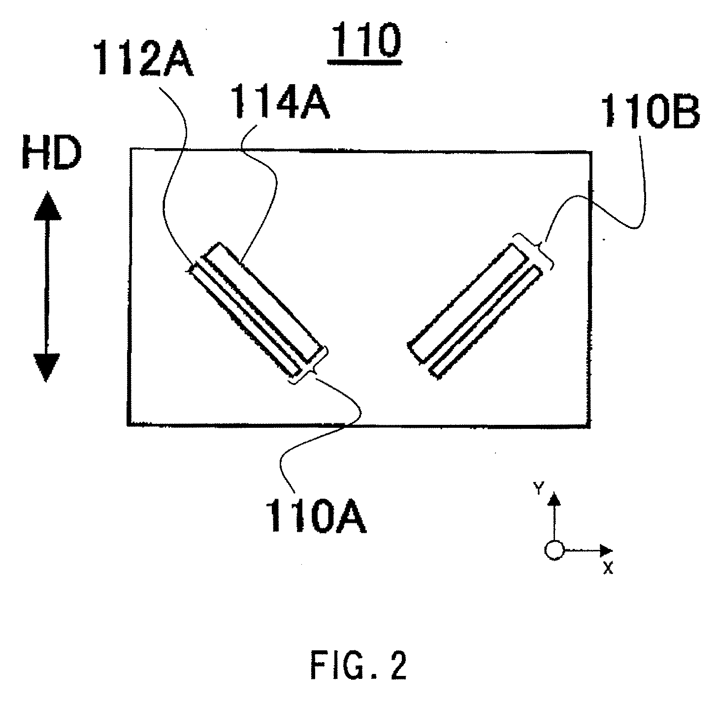
  • Measurement method and apparatus, exposure apparatus, and device manufacturing method
  • Measurement method and apparatus, exposure apparatus, and device manufacturing method
  • Measurement method and apparatus, exposure apparatus, and device manufacturing method

Examples


Embodiment Construction

[0026] Referring now to the accompanying drawings, a description will be given of a preferred embodiment of this invention. In each figure, the same reference numeral is assigned to the same component to avoid a duplicate explanation.

[0027] Referring to FIGS. 6 to 8, a description will now be given of the principle of the wavefront measurement by LDI (or the LDI measurement).

[0028] The LDI measurement arranges an object side measurement mark OM having a pair of parallel adjacent slits, i.e., slit OS1 and slit OS2, at an object side of a target optical system PO. A (slit) width in a shorter direction of at least one slit in the object side measurement mark OM, i.e., the slit OS1 in this embodiment, is made equal to or smaller than the resolving power of the target optical system PO at the object side. As shown in FIG. 7A, the width d of the slit OS, should preferably satisfy d≦0.5×λ / na, where na is a numerical aperture of the target optical system PO at the object side, and λ is a ...


PUM


Abstract

A measurement method measures a wavefront aberration of a target optical system using an interference pattern formed by lights from first and second image side slits. The first image side slit has a width equal to or smaller than a diffraction limit of the target optical system. The measurement method includes the steps of obtaining a first and second wavefronts having wavefront aberration information of the target optical system in ±45° directions relative to the polarization direction of the light, and calculating wavefront aberration of the target optical system based on the first and second wavefronts of the target optical system obtained by the obtaining step.

Description

BACKGROUND OF THE INVENTION [0001] The present invention relates generally to a measurement method and apparatus, and particularly to a measurement method and apparatus for measuring an optical characteristic of a projection optical system that projects a pattern of a reticle (mask) to a substrate. [0002] A projection exposure apparatus has so far been employed which uses the lithography technology to manufacture fine semiconductor devices such as a semiconductor device, e.g., an IC and an LSI, an imaging device, e.g., a CCD, a display device, e.g., a liquid crystal panel, a magnetic head. A projection exposure apparatus transfers a pattern of a reticle (mask) onto a substrate such a wafer via a projection optical system. Since the exposure apparatus is required to precisely transfer a pattern of a reticle to a substrate with a specified magnification, it is important to use a projection optical system that has an excellent imaging characteristic and a restrained aberration. Especia...

Claims


Application Information

Patent Timeline
IPC IPC(8): G01B9/00
CPCG01J9/02G03F7/706
Inventor TEZUKA, TARO
Owner CANON KK
Learn More